hai mas Bimo,I want to fill the blank components value on AKSA conceptual schematic. And then I begin to change the known value 😀 and add new components.
I also agree to reduce base resistor and reduce emitter resistor to 0.22 Ohm.
I enjoy learning how to optimize a design in simulator.
that's is very interesting.
I'm waiting for the real life one...
If you build it please take me too 🙂 (ngajak2 saya)
because I can't sim's & I don't have good equipment like yours
Regards
I'm sorry about your difficulties, Hugh. I hope you get better. If you want to look at what I've been up to lately, just for your own amusement, I think you'll find the Kuartlotron link in my signature interesting.
The base stopper resistance is divided by Hfe, so if your transistor has an Hfe of 100 and your base stopper is 10R, then it will be like having a 0.1R emitter resistor that's dependent on Hfe and also very inductive (due to transistor Cbe). If you want to be in the optimal bias zone, then the base stopper voltage drop should be added to the emitter resistor voltage drop, or your crossover point will be skewed by the base stoppers. Of course with smaller base stoppers this effect will be much less.
The base stopper resistance is divided by Hfe, so if your transistor has an Hfe of 100 and your base stopper is 10R, then it will be like having a 0.1R emitter resistor that's dependent on Hfe and also very inductive (due to transistor Cbe). If you want to be in the optimal bias zone, then the base stopper voltage drop should be added to the emitter resistor voltage drop, or your crossover point will be skewed by the base stoppers. Of course with smaller base stoppers this effect will be much less.
hai mas Bimo,
that's is very interesting.
I'm waiting for the real life one...
If you build it please take me too 🙂 (ngajak2 saya)
because I can't sim's & I don't have good equipment like yours
Regards
John, this is simple amp. You can see the layout example on my blog. But I know you can design PCB layout yourself.
We can discuss it in our local forum. May be we can replace our legendary OCL 150W with this one 😉
OK, I will try it with SMD this time 😀
May I ask which resistor should be 0,25watt or more...
btw, I'm planining to buy some 0,4watt SMD resistor 🙂
next month in the group buy...
just PM me if you need some too
May I ask which resistor should be 0,25watt or more...
btw, I'm planining to buy some 0,4watt SMD resistor 🙂
next month in the group buy...
just PM me if you need some too
The base stopper resistance is divided by Hfe, so if your transistor has an Hfe of 100 and your base stopper is 10R, then it will be like having a 0.1R emitter resistor that's dependent on Hfe and also very inductive (due to transistor Cbe). If you want to be in the optimal bias zone, then the base stopper voltage drop should be added to the emitter resistor voltage drop, or your crossover point will be skewed by the base stoppers. Of course with smaller base stoppers this effect will be much less.
We have discuss it on another thread 🙂
If I lowered base resistor on the emitter follower, I have a small peak around 10Mhz because small value of Cbe. Is this OK?
If I change the base resistors, the proportion of bootstrap resistor must be change to get H2 distortion dominant. But I can not make H2 distortion dominant below 7V peak output

Miller compensation can be lowered to get higher slew rate with still enough phase margin and gain margin 😎
OK, I will try it with SMD this time 😀
May I ask which resistor should be 0,25watt or more...
btw, I'm planining to buy some 0,4watt SMD resistor 🙂
next month in the group buy...
just PM me if you need some too
Almost all resistors are 0,25watt. Please see my blog, if I do not specify it, use 0,25watt.
I still searching the components. If I done I will PM. Thank you.
The VAS transistor's Early effect causes signal distortions mainly of H2. A very good transistor here like the C3503 will have very little Early effect so the H2 it creates will be swamped by load distortions in a circuit like this. So, try a worse transistor?
That pesky peaking is usually caused by Cbe, not reduced by it, and can be a difficult problem in even very simple amplifiers. You could try an RC from VAS collector to ground. I got around 470p+33R. However this loads the VAS, lowering slew rate and increasing distortion.
That pesky peaking is usually caused by Cbe, not reduced by it, and can be a difficult problem in even very simple amplifiers. You could try an RC from VAS collector to ground. I got around 470p+33R. However this loads the VAS, lowering slew rate and increasing distortion.
The VAS transistor's Early effect causes signal distortions mainly of H2. A very good transistor here like the C3503 will have very little Early effect so the H2 it creates will be swamped by load distortions in a circuit like this. So, try a worse transistor?
That pesky peaking is usually caused by Cbe, not reduced by it, and can be a difficult problem in even very simple amplifiers. You could try an RC from VAS collector to ground. I got around 470p+33R. However this loads the VAS, lowering slew rate and increasing distortion.
I see. Then I use the original value of base resistors. It is not give pesky peaking, although it reduce open loop gain a little bit. But if I reduce the base resistors, I can use RC to loading the VAS, but reduce slew rate and increase distortion. 🙄
Member
Joined 2009
Paid Member
I also did a 'clone' of the AKSA. It's not exact because I didn't have all the information at the time and when I did have it, I couldn't reveal it, but my design has component values that are quite close to the original and may provide you with a good starting point for your own experiments: http://www.diyaudio.com/forums/solid-state/140461-tgm-amplifier.html
go to post 356 for the as-built schematic and don't ignore the needs for a good power supply.
go to post 356 for the as-built schematic and don't ignore the needs for a good power supply.
Attachments
Last edited:
I also did a 'clone' of the AKSA. It's not exact because I didn't have all the information at the time and when I did have it, I couldn't reveal it, but my design has component values that are quite close to the original and may provide you with a good starting point for your own experiments: http://www.diyaudio.com/forums/solid-state/140461-tgm-amplifier.html
go to post 356 for the as-built schematic and don't ignore the needs for a good power supply.
Thank you, Bigun.
a 2k2 probably has a tolerance of +-10%
Your 2k is nominally inside that 2k2 tolerance range.
Use it.
Your 2k is nominally inside that 2k2 tolerance range.
Use it.
D
Deleted member 148505
D
Deleted member 148505
R12 and R12B already sets the maximum bias. So even if you mistakenly set the trimpot to 0 ohm, the output stage will not blow.
R12 and R12B already sets the maximum bias. So even if you mistakenly set the trimpot to 0 ohm, the output stage will not blow.
I'll try it thanks
R11 @ 1k5 and R12 @ 330r results in a Vbe ratio of 5.545:1
With a Vbe of 700mVbe you end up with a bias voltage of 3.88V
That is too high. The output stage could run far too hot.
It depends on the Vbe of the multiplier and the drivers and the outputs.
With 200r trim pot added and set to maximum, the ratio drops to 3.83:1 giving a bias voltage of ~2.68V if Vbe=700mVbe
That is still too high for first start up.
Planning to finisch my BAksa with special thanks to Greg Erskin the boards are provided by him,question regarding the trimpot.Normaly it is 2K2 but can I use a 2K ?
Hi meanman1964,
Great to see you are nearly there.😀
Here are the values that I am aware of from a couple of real AKSA 55s and my BAKSA 55.
Note: R12 and R12B are in series and I believe the 2 resistors in series were used to allow fine tuning/tweaking.
R11 (AKSA and BAKSA) = 1k5
R12 (AKSA and BAKSA) = 330
R12B (AKSA and BAKSA) = 150
P1 (AKSA) = 100
P1 (BAKSA) = 1k
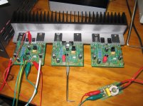
I think the 1k shown on the BAKSA schematic is actually a typo, but if you look at the photos you can see that I used 1k pots.
Using a 1k will make the fine adjustments of the bias a little more difficult but it is still doable.
If you use a 100 ohm pot you may need to adjust R12/R12B.
Looking at AndrewT's last post (and including R12B) I think the values of the original design are correct.
regards
Greg
Planning to finisch my BAksa with special thanks to Greg Erskin the boards are provided by him,question regarding the trimpot.Normaly it is 2K2 but can I use a 2K ?
Thanks for your help you guys
Sorry for the miss understanding but I messed up two amps.The question was for the ANC340 of Greg.😱
Thanks for your help you guys
Sorry for the miss understanding but I messed up two amps.The question was for the ANC340 of Greg.😱
I think you are one of a few that knows about it....and probably the first to build it.
a 2k2 probably has a tolerance of +-10%
Your 2k is nominally inside that 2k2 tolerance range.
Use it.
I agree. Try the 2k and let me know.
regards
- Home
- Amplifiers
- Solid State
- Based on Hugh Dean's AKSA 55