Bonsai,
If that is a problem why not just add a buffer in front of the input section?
That is what the "gnome "(or "NX") is. this amp with a buffer.
(below) ... at a few uA IP base current , I would say we are still Hi-Z here.
No need for a buffer ?? 😕
PS - diamond buffer is pA range , but ... (pA-uA) , I would feel sorry for the
source that could not drive either .
Edit - 2sD667a/2sb647a are the more "robust" TO-92L IP pair I was referring to.
Mouser has several more that have 120v Vceo/10Cob/ 1A-1w ratings. No heatsinks needed
for these devices.
OS
Attachments
Last edited:
Bonsai,
If that is a problem why not just add a buffer in front of the input section?
Exactly.
It's not called a diamond buffer for nothing.
🙂
OS,
Could you then make the Gnome without the servo like you just did with the CFA-XH or would you still need to include it?
Could you then make the Gnome without the servo like you just did with the CFA-XH or would you still need to include it?
Well, couple of uA is no problem (I checked the input current at my design - 2.42uA RMS). Bonsai's initial comment was more related to the "classic" design with CCSed diodes, I believe...
OS,
Could you then make the Gnome without the servo like you just did with the CFA-XH or would you still need to include it?
The diamond really "goes well" with the servo.
The VSSA is far less sensitive to P-N gender mismatches. I swapped
models even ... Offset is much better than with the buffer.
With the HD input pair , reliability should be very good .
The only downside to the VSSA is a slight LF (high output) offset ...without servo.
But 20mv is not bad. With no input , offset is 1-2mv .
About as good as a non-servo'ed bootstrapped "LIN".
Easy like a early "DX amp" , but much better performance. Builders
will "flock" 😀
OS
OS,
So it seems now that you would lean towards the CFA-XH over the Gnome at this point. Less parts and seems like could be a more musical sound.
So it seems now that you would lean towards the CFA-XH over the Gnome at this point. Less parts and seems like could be a more musical sound.
OS,
So it seems now that you would lean towards the CFA-XH over the Gnome at this point. Less parts and seems like could be a more musical sound.
Gnome is really good , thimios built BOTH servo'ed editions with
VERY good tests.
This one (with vzaichenko's shunt) really goes to the "limit".
I saw his work - and took "a leap of faith".
I'm still trying to figure why? shunt comp. works so much
better with the VSSA/Hawksford combo.
Different proportions of the resistive shunt and the capacitive
will give either lower total THD or less (different) H5-7 ....
I'm still playing.
I did this combo before with other compensations and did not
even come close to single digit PPM- 700V/us slew.
OS
Well, couple of uA is no problem (I checked the input current at my design - 2.42uA RMS). Bonsai's initial comment was more related to the "classic" design with CCSed diodes, I believe...
Correct. I was referring to the schematic Richard Marsh posted. The VSSA and classic CFA diamond do not have input bias current problems.
BTW with a conventional diamond buffer input stage, if the base 'lift' resistors are appropriately set, there are no offset or bias issues. 120 to 150 mV is about right for the base lift.
I guess the only way to know will be to listen to both of them and decide which we like better then. Seems like the Gnome is finished but are you still playing with this latest CFA-XH?
Up to now we calibrated many FO modules and all can be trimmed down to +/-1 mV, surprisingly they stay within the limits even at +60°C. DC servo is out of the question here.
What I miss here is more listening tests and evaluations between minor sch variants, not every change on the paper will result in better sound performance, critical listening comparisons are crucial to make firm step forward in sch.
What I miss here is more listening tests and evaluations between minor sch variants, not every change on the paper will result in better sound performance, critical listening comparisons are crucial to make firm step forward in sch.
Servo is still valid, unless you go for AC-coupled input, for IRL applications you don't know the condition of your input signal.
Servo is still valid, unless you go for AC-coupled input, for IRL applications you don't know the condition of your input signal.
Exactly. In many cases, if you use DC coupling, DC servo compensates not only the power amp offset drift, but also all the offsets and their possible slow fluctuations, coming from the previous stages.
As a genberal observation, these CFA amps tend to be better DC stability wise than VFA's. The main reason is because of the delta Vbe cancellation taking place in the front end - especially with the diamond version. I am amazed at how CFA power amp can settle to within 1-2 mV repeatabley after many power up/down cycles with no servo and fully DC coupled.
not a CFA advantage - again
once again an absurd claim of "CFA" advantage - a diff pair with identical matched Q, operating at near identical Ic, will match in Vbe, TC, cancel better than complementary Q, at best diamond inputs with 2 complementary pairs end up no better than the VFA matched diff pair
the VFA diff pair is much simpler to get matching/TC cancellation with fet input Q compared to the complementary fet input "CFA" design
you then have some simple engineering to obtain the full benefits of that fundamental input matching advantage of VFA - keep Vce(ds) the same - which some VFA diff pair collector load/VAS input circuits don't - but there are others that do match this very well - cascoding the input Q can help too
op amp textbook design for low input offset in precision op amp circuits further recommend balanced gain in the next stage too - diff pair VAS does this well - in addition to providing huge DC gain needed to servo the output stage offset
all these techniques are there to be seen in Cordell's 1984 "A MOSFET Power Amplifier with Error Correction"
Last edited:
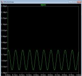
OK, here are some simulations:
4 pictures with sine wave 20Hz, 1kHz, 20kHz, 50kHz
4 pictures with square - same 20Hz, 1kHz, 20kHz, 50kHz
1 picture with 1 kHz spectrum
1 picture with open loop (no compensation either)
It will be possible to audition the prototype open loop - linear enough for decent sound 😉
Valery, thanks for the simulation.
I started to simulate your amp and first simulation shows that is unstable??
BR Damir
Could be that I miss some current, VAS or output current?
PC it was missin one connection, but still unstable.
Attachments

Last edited:
once again an absurd claim of "CFA" advantage - a diff pair with identical matched Q, operating at near identical Ic, will match in Vbe, TC, cancel better than complementary Q, at best diamond inputs with 2 complementary pairs end up no better than the VFA matched diff pair
the VFA diff pair is much simpler to get matching/TC cancellation with fet input Q compared to the complementary fet input "CFA" design
you then have some simple engineering to obtain the full benefits of that fundamental input matching advantage of VFA - keep Vce(ds) the same - which some VFA diff pair collector load/VAS input circuits don't - but there are others that do match this very well - cascoding the input Q can help too
op amp textbook design for low input offset in precision op amp circuits further recommend balanced gain in the next stage too - diff pair VAS does this well - in addition to providing huge DC gain needed to servo the output stage offset
all these techniques are there to be seen in Cordell's 1984 "A MOSFET Power Amplifier with Error Correction"
Thanks, jcx,
I agree with all you've said 🙂
Cheers,
Bob
bias current offset, TC may be a concern with hi Z volume pot input or high shunt R with AC coupling - not at all with buffered low Z DC coupled drive, or less an issue with matched source and feedback DCR
there is some potential for bias current cancellation with diamond (or complementary diff pair for VFA)
but how many are using hfe matched complements - modern IC designers may be able to control BJT parameters closely and take advantage but does it apply to discrete amp builders
there is some potential for bias current cancellation with diamond (or complementary diff pair for VFA)
but how many are using hfe matched complements - modern IC designers may be able to control BJT parameters closely and take advantage but does it apply to discrete amp builders
Last edited:
Having built both CFA and VFA's, I understand that both comments on dc offset/drift seem to be correct (Bonsai and jcx). The CFA is very stable with time and temp. It is easier to find pairs that match in VFA than CFA. Other than that, the CFA is very stable in ac and dc. Esp CFA that are simple topologies with few parts. Again, in my experience, the CFA does better, though, and with what seems like less work.
jcx -- I always use matched compl.... for lowest distortion and for Ib cancellation. For VFA, I use monolithic duals.
[If you use compl jFETs on the input and run them at thier zero TC current, direct coupled, the drift is extreamly low.]
THx-RNMarsh
jcx -- I always use matched compl.... for lowest distortion and for Ib cancellation. For VFA, I use monolithic duals.
[If you use compl jFETs on the input and run them at thier zero TC current, direct coupled, the drift is extreamly low.]
THx-RNMarsh
Last edited:
Valery, thanks for the simulation.
I started to simulate your amp and first simulation shows that is unstable??
BR Damir
Could be that I miss some current, VAS or output current?
PC it was missin one connection, but still unstable.
In your first schematic you use wrongly connected C10, C11 instead to be MIC.
I tried both, increased C10, C11 to 100 pF but still it oscillates.
Valery, pity you use Multisim and we can't interchange the files . Maybe you can try LTspice, I think it's better, at least it can simulate to 0.000000 % distortion.
Damir
Last edited:
In your first schematic you use wrongly connected C10, C11 instead to be MIC.
I tried both, increased C10, C11 to 100 pF but still it oscillates.
Valery, pity you use Multisim and we can't interchange the files . Maybe you can try LTspice, I think it's better, at least it can simulate to 0.000000 % distortion.
Damir
Hi Damir,
Attached is schematic with the values I used for simulation presented earlier.
In Multisim it shows no problem with stability.
You're right about the mistake in initial schematic - result of manual transfer from Multisim to Diptrace. So it is copied on the PCB 🙁( Thanks for pointing it out.
If the specified compensation values don't improve the situation, you can try increasing NFB network values (R6/R9) proportionally - higher values will provide a bit higher distortion, but also higher stability margin. The ones I use push it close to the limit. It will be interesting to see where you end up in your simulation.
I will try to move to LTSpice - from what I see, it allows more flexibility, but look like less convenient in terms of user interface (probably I'm just not familiar with it as yet).
BTW, if somebody has got SPICE models for Sanken transistors (2SC4382/2SA1668, 2SC2922/2SA1216) - they would be very much appreciated. I use them in live prototypes, but have to substitute them in simulation. Previous prototypes showed such substitution works good enough, however having original models (or at least better ones) would be great.
Best regards,
Valery
Attachments

- Home
- Amplifiers
- Solid State
- CFA Topology Audio Amplifiers