I like the tunnel. Bet it's better than fins out as there may be a multiplying action. Looks like there would be enough draft to even place the PS and trani on the bottom - for a smaller chassis. Hope you continue on the build and post the results.
A Member used an upright PC chassis as an amplifier case.
The top two thirds was just tubes through the roof of the case.
All the amp was in the bottom third.
He posted a description and many pics. Maybe about 7 or 8years ago.
The chimney effect of the ~200mm high/long tubes created sufficient draught to cool the amplifier adequately.
The top two thirds was just tubes through the roof of the case.
All the amp was in the bottom third.
He posted a description and many pics. Maybe about 7 or 8years ago.
The chimney effect of the ~200mm high/long tubes created sufficient draught to cool the amplifier adequately.
I think I found it http://www.diyaudio.com/forums/solid-state/119958-1000-watt-sub-amp-design-build-2.html#post1469312
Maybe not, it's with fans
Running "without" fans (only one) a few pages later
http://www.diyaudio.com/forums/solid-state/119958-1000-watt-sub-amp-design-build-12.html#post1519002
Maybe not, it's with fans
Running "without" fans (only one) a few pages later
http://www.diyaudio.com/forums/solid-state/119958-1000-watt-sub-amp-design-build-12.html#post1519002
Last edited:
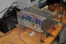
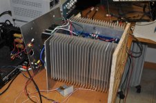
I verified my conjecture about the chimney effect of the heatsinks mounted fin-to-fin in my F4 amplifier. Each channel is biased to 1.36A with 22.6V rails for a total of about 125W total dissipation. I measured ambient and heatsink temperatures for two configurations: fin-to-fin and fins outward as shown in the photos. The temperatures shown were after more than one hour and were stable.
fin-to-fin fins-outward
ambient: 20.1C 20.1C
left channel: 42.3C 44.9C
right channel: 42.3C 44.9C
<sorry - I cannot figure out how to present a table with this "editor">
fin-to-fin fins-outward
ambient: 20.1C 20.1C
left channel: 42.3C 44.9C
right channel: 42.3C 44.9C
<sorry - I cannot figure out how to present a table with this "editor">
Attachments
Last edited:
nice test 
there is a 3. option
fins outward and 'enclosed' with a panel to create the convection effect
but fins to fins looks great 😉
simpler to assemble giving easy access to amp boards etc
there is a 3. option
fins outward and 'enclosed' with a panel to create the convection effect
but fins to fins looks great 😉
simpler to assemble giving easy access to amp boards etc
a 2.6 C degree drop down to T s-a of 22.2 C degrees is mighty impressive.
I note that the sinks are quite tall. This efficiency improvement may tend to be more effective for tall sinks and may become very effective with very tall sinks.
The speed of airflow is due to the difference in pressure at the top & bottom of the "chimney".
It's the "speed" of the airflow that reduces the thickness of the laminar layer attached to the fin surface.
From The Advertising Dept.🙄
A new small footprint F5 on the way - first run.
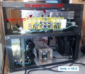
Developments on a horizontal format liquid cooled chassis are progressing. This is a JFET-BJT Cascode input with 12 output transistors and the temps are very encouraging. This PCB is 230 mm long and the F5 is 170 with fewer devices. That suggests the F5 LC chassis will come in at ~ 9" deep x 7" wide x 8" high.
The heat transfer will be much better as this experimental build just uses ceramic pads with no compound. I'll post in the LC thread when the final F5 version is completed - should be a nice set in a very small package.
A new small footprint F5 on the way - first run.
Developments on a horizontal format liquid cooled chassis are progressing. This is a JFET-BJT Cascode input with 12 output transistors and the temps are very encouraging. This PCB is 230 mm long and the F5 is 170 with fewer devices. That suggests the F5 LC chassis will come in at ~ 9" deep x 7" wide x 8" high.
The heat transfer will be much better as this experimental build just uses ceramic pads with no compound. I'll post in the LC thread when the final F5 version is completed - should be a nice set in a very small package.
Attachments
Last edited:
the down side
-Heat travels through aluminum hundreds of times faster than through epoxy.
-A heatsink for an F5 channel has hundreds of times more exposed surface than a power FET.
-The package of a TO-247 has a thermal resistance between case and ambient of > 40C/W.
-Thermal resistance to ambient of the exposed epoxy of a TO-247 device is several times that number.
- Thermal conductivity of air is total suck grade !
=> of the +30W dissipation of a power FET in an F5 channel, only a tiny fraction will be exchanged between the top of the device and ambient air.
(aka, the top of a power FET may measure a high temperature, but heat exchange with the air around it will be zilch)
Thanks !!
Excellent explanation !
🙂
Excellent explanation !
🙂
-Heat travels through aluminum hundreds of times faster than through epoxy.
-A heatsink for an F5 channel has hundreds of times more exposed surface than a power FET.
-The package of a TO-247 has a thermal resistance between case and ambient of > 40C/W.
-Thermal resistance to ambient of the exposed epoxy of a TO-247 device is several times that number.
- Thermal conductivity of air is total suck grade !
=> of the +30W dissipation of a power FET in an F5 channel, only a tiny fraction will be exchanged between the top of the device and ambient air.
(aka, the top of a power FET may measure a high temperature, but heat exchange with the air around it will be zilch)
I verified my conjecture about the chimney effect of the heatsinks mounted fin-to-fin in my F4 amplifier. Each channel is biased to 1.36A with 22.6V rails for a total of about 125W total dissipation. I measured ambient and heatsink temperatures for two configurations: fin-to-fin and fins outward as shown in the photos. The temperatures shown were after more than one hour and were stable.
fin-to-fin fins-outward
ambient: 20.1C 20.1C
left channel: 42.3C 44.9C
right channel: 42.3C 44.9C
<sorry - I cannot figure out how to present a table with this "editor">
While I agree that 2.6ºC is a real and useful difference, I would suggest that the 'chimney effect' is not making ALL the difference here.
If we agree that the hottest place(s) on the HS is immediately next to the output transistor(s), then orienting that face (and the output devices themselves) outward and into the ambient air would cool the HS more than facing them inward where they are relatively more 'shielded' or 'enclosed' from ambient air.
With the fins outward, there is plenty of airflow for cooling the plastic sides of the output FETs, but the air to plastic thermal efficiency is extremely low. I haven't performed the experiment, but I predict that separating the outward fin heatsinks by an arbitrary distance would not make a measurable difference in the temperature.
The chimney effect is well documented. This paper compares heatsinks with "open" fin designed to closed extrusion designs which are similar to my fin-to-fin arrangement. http://www.crydom.com/en/Tech/Whitepapers/HS_WP_FA.pdf.
The chimney effect is well documented. This paper compares heatsinks with "open" fin designed to closed extrusion designs which are similar to my fin-to-fin arrangement. http://www.crydom.com/en/Tech/Whitepapers/HS_WP_FA.pdf.
While I agree that 2.6ºC is a real and useful difference, I would suggest that the 'chimney effect' is not making ALL the difference here.
If we agree that the hottest place(s) on the HS is immediately next to the output transistor(s), then orienting that face (and the output devices themselves) outward and into the ambient air would cool the HS more than facing them inward where they are relatively more 'shielded' or 'enclosed' from ambient air.
Alright, your HS looks to be about 7 inches tall, so that's a respectable chimney.
I've been reading a book on heat transfer by Tony Kordyban, and I took away two lessons: If you know it's going to get hot, design for a fan from the beginning. It has gone against my purist nature to run a fan, but I will try to work one in for the next amp. All it takes is a light puff.
And lesson two is that even as good as Kerafol pads are, those rubber things are a huge impediment to moving heat. So instead I suggest each power transistor gets mounted to its own electrically isolated aluminum hs, so in-effect a chimney made of isolated fins w a very slow running fan (VSRF) at the bottom.
........
And lesson two is that even as good as Kerafol pads are, those rubber things are a huge impediment to moving heat.....
Is anyone aware of a manufacturer that tried or considered coating/insulating the face of mosfets in their production line - like the LM3886TF? Seems like a logical solution.
Yes, the heatsinks are 7" tall, 10" wide, with 2.5" fins. I have used the tunnel configuration with very low noise Noctua fans and get about 3X improvement in cooling efficiency, i.e. a drop of about 3 in thermal resistance.
Alright, your HS looks to be about 7 inches tall, so that's a respectable chimney.
I've been reading a book on heat transfer by Tony Kordyban, and I took away two lessons: If you know it's going to get hot, design for a fan from the beginning. It has gone against my purist nature to run a fan, but I will try to work one in for the next amp. All it takes is a light puff.
And lesson two is that even as good as Kerafol pads are, those rubber things are a huge impediment to moving heat. So instead I suggest each power transistor gets mounted to its own electrically isolated aluminum hs, so in-effect a chimney made of isolated fins w a very slow running fan (VSRF) at the bottom.
like the LM3886TF? Seems like a logical solution.
You is an amusing guy.
Meaning ??? 😕 Don't want to hijack the thread, but are you aware of a reason a dielectric layer can't or shouldn't be applied during manufacturing. There may be one but I haven't heard or read an explanation.You is an amusing guy.
- Home
- Amplifiers
- Pass Labs
- F5 power amplifier