..... If you had instantaneous heat spread it wouldn't matter at all where to mount.
but you have not ...... at least when we are speaking about heatsinking systems working in 50-55C range , which is , by experience , most economic solution (in other words ,+25C above ambient temp)
of course that entire issue is nonexistent if you'r eusing Eiffel Tower to cool 2 x 100W of dissipation

though ..... in that case , output devices will certainly be cooler mounted on top

Patrick K. (EUVL) wrote an article for Linear Audio (with simulations and measurements) and came to the same conclusion as Zen Mod.
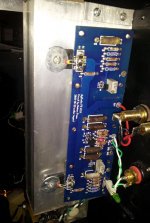
If you use a simple Right Angled bracket to support those pcbs, you can more easily adjust the trimpots from above after assembly, and can also shorten the wires from the power supply, etc, etc - otherwise not much heat distribution difference, as noted above.
Just go for it ...
Just go for it ...
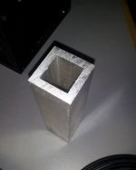
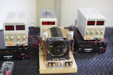
My screw-up might add a little perspective here. This liquid cooled build uses eight inches of square tube with 1/4" walls. By mistake it ran for hours with the cooling off. Don't know how hot it got but the amp was and still is stable and sounding great. In this case the heat spread was probably most significant - though there was obviously some convection with the vertical format.
Could not get away with that with more transistors like a BA, but the F5 really isn't a fire breather - correct?
Could not get away with that with more transistors like a BA, but the F5 really isn't a fire breather - correct?
Attachments
I really found itPatrick K. (EUVL) wrote an article for Linear Audio (with simulations and measurements) and came to the same conclusion as Zen Mod.
http://www.linearaudio.net/images/stories/Didden LA V3 PK lr.pdf
Now I could still doubt because his heatsink is not so high and much wider ... 😱
O right, but maybe it would actually work? 😛Not actually a chimney as the tube is sealed on both ends.
There are some good examples of both the chimney and chimney with small fan earlier in the thread. You'll have to did them out if interested in doing one.. 
Here are two examples: http://www.diyaudio.com/forums/pass-labs/213152-balanced-f5-small-footprint.html#post3033429 http://www.diyaudio.com/forums/pass-labs/121228-f5-power-amplifier-1021.html#post2453420
There are some good examples of both the chimney and chimney with small fan earlier in the thread. You'll have to did them out if interested in doing one..
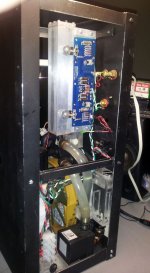
The tunnel that Nelson shows us is very simular to mine. I use it for my F5 V3 Turbo. I have tried both channels to run with low bias. I will mount a therminal cut, 55 C I think, before I raise bias to 310mV over two 1ohm in parallel. Transformer is 660VA with 2x33V AC. Is a therminal cut safe enought, or must a kind of electronics be added??
Eivind Stillingen
Eivind Stillingen
Very nice Lynn, I missed that thread and there is a lot of useful and fun information there. Haven't read all the posts yet, but do you have any general comments on how being balanced effected the F5 output? Planning to try that with a BA-3 this spring.
__________________
Bob M.
"Arrange Whatever Pieces Come Your Way."
dieringe:
And how long would that sink have to be? And how many outputs had you needed to spread the heat over that sink? I think the answer would terrify you.
Its not much to gain lenghtwise. You only gain about 40% capasity by doubling the lenght. It's in the width you find the gain. Doubling the width gives you 100% more cooling capasity.
So if you were to cut that long sink in say 4 smaler parts and placed them side by side, you would gain much more colling capasity.
Ex: if you had a 25cm long sink as benchmark. If you made that one 100cm long, you would gain 80% colling capasity. If you cut that sink in to 4 25cm pc and placed them side by side, you would gain 400% cooling capasity.
Last edited:
Something like this Solar updraft tower - Wikipedia, the free encyclopediaAnd how long would that sink have to be?
Recover energy by turbines, feed back into ampilfier.
The heating devices should be in the upper region of the heatsink anyway ...
Only with the air, so the hotter area should be at the top
No, no and no.I think I've read that somewhere in Papa's papers, long ago. 😀
As this was counterintuitive to me as well I assumed it was tested and tried to explain it to myself by the better airflow you get if the center of heat is higher and the hottest air leaves the heatsink as soon as possible.
Right?
...............would be better for heat distribution?
( PS: My devices are a bit lower than half way, not at the bottom... )
Yes and no.if devices are situated in one row on heatsink , they need to be horizontally on lower third
.............
About 40% up from the bottom for a single row of devices.
Obviously. But where😕NoOriginally Posted by dieringe
I think I've read that somewhere in Papa's papers, long ago.
Here is one more example of my favorite tunnel heatsink arrangement which is shown without the use of fans. http://www.diyaudio.com/forums/pass-labs/216616-f6-amplifier-510.html#post3575862 The reason I like it is that the chassis is extremely simple to build and the PCBs are easily accessible for tweaking and modification.
I need to do some tests, but I suspect that the passive (convection cooled) fin-to-fin heatsink arrangement has a thermal efficiency as good as or better than the "ordinary" arrangement with the heatsink fins pointed outward from the sides of the chassis. This may not seem logical, but the tunnel just might improve the airflow. I dunno for sure, but some experiments are in order. I just need to turn the heatsinks around to face the fins outward.
I need to do some tests, but I suspect that the passive (convection cooled) fin-to-fin heatsink arrangement has a thermal efficiency as good as or better than the "ordinary" arrangement with the heatsink fins pointed outward from the sides of the chassis. This may not seem logical, but the tunnel just might improve the airflow. I dunno for sure, but some experiments are in order. I just need to turn the heatsinks around to face the fins outward.
There are some good examples of both the chimney and chimney with small fan earlier in the thread. You'll have to did them out if interested in doing one..
- Home
- Amplifiers
- Pass Labs
- F5 power amplifier