Two pictures without any word
Any word about sonic difference?
Any word about sonic difference?
Up to now ,i can't hear any difference,except a little noise(ear in touch with speaker)on VSSA.
Please read this.The Sound of Audio Amplifiers: Can you hear a difference between Amps? | Audioholics
Thimios.
Yes, I have read a larger amount of opinions about the phenomenon of the experience of sound. In the end, I can only rely on what I've noticed or experienced.
I think that this experience is really very subjective. And unexpected.
For example, comparing two different amplifiers, expecting audible difference, comes that I can not define it if the volume is equally set. On the other hand, when change elements in identical circuits, changes become audible. And that when results of the simulator are almost identical.
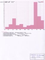
According to pictures one would expect no differences, so I wonder if it is true sonically.
I think that this experience is really very subjective. And unexpected.
For example, comparing two different amplifiers, expecting audible difference, comes that I can not define it if the volume is equally set. On the other hand, when change elements in identical circuits, changes become audible. And that when results of the simulator are almost identical.
According to pictures one would expect no differences, so I wonder if it is true sonically.
Yes, I have read a larger amount of opinions about the phenomenon of the experience of sound. In the end, I can only rely on what I've noticed or experienced.
I think that this experience is really very subjective. And unexpected.
For example, comparing two different amplifiers, expecting audible difference, comes that I can not define it if the volume is equally set. On the other hand, when change elements in identical circuits, changes become audible. And that when results of the simulator are almost identical.
According to pictures one would expect no differences, so I wonder if it is true sonically.
if you have ears like Spock make the difference .I have same ears like Spok.😉
if you have ears like Spock make the difference .I have same ears like Spok.😉
I have a friend who can only hear no more than 13kHz in medical test. Mine beyond of that in medical test 😎

Franken SlewMonster
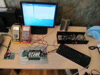
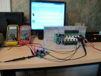
Just for giggles I grafted on a VSSA board as an IPS, lo and behold it works. Testing has to be short and sweet at the moment since it still is not on a real heat sink yet. Seems to be a little over-compensated thermally, but then I did let the assembly get quite hot. This is likely a good thing at the moment.
Just for giggles I grafted on a VSSA board as an IPS, lo and behold it works. Testing has to be short and sweet at the moment since it still is not on a real heat sink yet. Seems to be a little over-compensated thermally, but then I did let the assembly get quite hot. This is likely a good thing at the moment.
Attachments
Hi Jason... that's is very nice
I've a pair PeeCeeBee left...
you know what it will be 😀
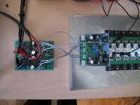
look at that dummy load, with heatsink is that 4 ohm
I've a pair PeeCeeBee left...
you know what it will be 😀
look at that dummy load, with heatsink is that 4 ohm
The test supply is only +/-32V. I like to test on small PSUs first then ramp things up. I will put together one that can allow full testing to about +/-80V.
Speaking of 'ramping it up', this HS will be the monsters new home shortly. I've only one question...
The heat sink is a composite of three sections. I have the choice of either 3 pair plus the VBE on the middle section with the remaining two pair on an adjacent section, or two pair on the same section as the VBE and three pair on an adjacent section. I'm inclined to think for best thermal compensation I'd want three pair on the same section as the VBE. Thoughts?
Attachments

Aluminum plate for thermal compound all three sections?
Possible. I'm just trying to work with what I have on hand without going out and buying a bunch of new metal. This is a test set-up at the moment. Ideally I will get some of the HeatSinkUSA 10.08" sections for a final 'permanent' build.
Just for giggles I grafted on a VSSA board as an IPS, lo and behold it works. Testing has to be short and sweet at the moment since it still is not on a real heat sink yet. Seems to be a little over-compensated thermally, but then I did let the assembly get quite hot. This is likely a good thing at the moment.
This was my goal in designing the OPS. Being able to take any project
here at DIYA (even a badger) , and tying it in to a neutral power section
for evaluation.
If anything really "catches your ear" ... standardize it as a IPS. 😎
OS
The test supply is only +/-32V. I like to test on small PSUs first then ramp things up. I will put together one that can allow full testing to about +/-80V.
Speaking of 'ramping it up', this HS will be the monsters new home shortly. I've only one question...
The heat sink is a composite of three sections. I have the choice of either 3 pair plus the VBE on the middle section with the remaining two pair on an adjacent section, or two pair on the same section as the VBE and three pair on an adjacent section. I'm inclined to think for best thermal compensation I'd want three pair on the same section as the VBE. Thoughts?
At least use thermal compound on the angles ... so if there is a Vbe
"current hogging" scenario on the last 2 pairs , the heatsink as a whole
will stabilize thermally to some degree (from section to section).
PS - R104 on the OPS sets the global Vbe co-efficient and R105 sets just the driver Vbe CE.
The original HK680 used similar Vbe to-126 devices but had the to-220 toshiba's as drivers.
Some tweaking might be required for "monster" drivers.
OS
Last edited:
Well this is what I ended up doing... Three pair and the VBE on the centre, two on the end, the third is just for show, and the fact I have a bunch of these heat sink sections.
Seems good thermally, 26mV across Re cold and 21.5mV when warm. Slightly over compensated but I'm OK with that for the moment.
Seems good thermally, 26mV across Re cold and 21.5mV when warm. Slightly over compensated but I'm OK with that for the moment.
Attachments
Is there any reason we can't fly the VBE on wires and mount on top of one of the outlets?
Thanks, Terry
Thanks, Terry
Is there any reason we can't fly the VBE on wires and mount on top of one of the outlets?
Thanks, Terry
You could do that , but this is not a DX or badger (EF2). Keep the wires short.
Much higher Z with a EF3.
That is why my Vbe's are VERY close to the drivers/OP's.
Using the base design (HK680) as a reference ....
The driver Vbe is "sandwiched" between
the to-220 drivers (wrapped with heatshrink), and the OP Vbe is just
4 cm away (from the drivers) on the main HS and 2cm away from one of the Sanken output devices. We are much closer on the slewmaster.
OS
- Home
- Amplifiers
- Solid State
- Slewmaster - CFA vs. VFA "Rumble"