Forwarded question
Hi,
Thank you for the PM
As explained:
both options A and B are fine but B also gives galvanic isolation the Teleporter.
However, please note that the isolator and preceding devices introduces jitter, so you may want to re-clock after isolation. In this regard, the SO3 board is elegant with the convenience of the XO on board. As you have indicated you would also like to use Ian's FIFO before the DAC. In this case the FiFO has its own isolator plus reclocker so the SO2/3 board is redundant - straight connection after OTTO to Ian's FIFO
I'm setting my source up to be able to switch between a USB-to-I2S device (Amanero) and an embedded player (e.g. BBB). The latter will reside in a separate box with its I2S output "teleported" (TM 😛) to the D/A.
Parts are ordered and I'm now trying to choose between the attached layouts.
Will the Teleporter offer adequate isolation (Option A), or should I play it safe and isolate at the OTTO's output (Option B)? 😉
Hi,
Thank you for the PM
As explained:
both options A and B are fine but B also gives galvanic isolation the Teleporter.
However, please note that the isolator and preceding devices introduces jitter, so you may want to re-clock after isolation. In this regard, the SO3 board is elegant with the convenience of the XO on board. As you have indicated you would also like to use Ian's FIFO before the DAC. In this case the FiFO has its own isolator plus reclocker so the SO2/3 board is redundant - straight connection after OTTO to Ian's FIFO
Last edited:
Just realized that if you are planning to stream DSD audio from BBB or Amanero then unfortunately, Ian's FIFO does not currently support DSD.
So it will be SO3 then that passes thru all formats.
So it will be SO3 then that passes thru all formats.
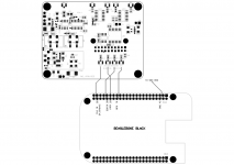
Interfacing S03 to BeagleBone Black
For those who have BBB - connection as shown for full synchronous clocking. No cape necessary.
On-board clock of the BBB should be disabled (or removed) and use appropriately divided clock from S03 instead.
Currently BBB has single 24.576MHz clock support only so only one S03 XO (49.152MHz or 98.304MHz) needs to be mounted or enabled. If 98.304MHz used then you get 'Turbo' Sync capability to 9018 DACs. Of course other DACs like PCM1794 also possible with BCK out from S03 as MCK'
Sample frequencies are limited to 48K, 96K and 192K as result of this single clock of the BBB. If future versions allow dual audio clocks then full range of sample frequencies will be possible and then CKSEL can be used to automatically switch.
Until then upsampling 44.1k-based audio files using software utility is a suitable option
Attachments
S03 and Doede dac
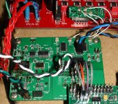
I'm using the raspberry pi and multi-purposing the S03 (which BTW, is a very flexible design, thanks Acko) with Doede's dac. Per Acko's instructions, I put a 100mhz Crystek in X1 and jumpered R18 to disable X2. Probably the BBB will sound better, but for those using the rpi, this is a *great* solution! This is the best the rpi has sounded with Doede's dac and I prefer it the usb->i2s solutions.
Acko's support, as always, is outstanding... 😉
Attachments
Actually, thank you for your painstaking efforts!
Honestly, I thought RPi was kid's stuff with little capability for the serious audio that we are involved
Honestly, I thought RPi was kid's stuff with little capability for the serious audio that we are involved
Last edited:
I'm using the raspberry pi and multi-purposing the S03 (which BTW, is a very flexible design, thanks Acko) with Doede's dac. Per Acko's instructions, I put a 100mhz Crystek in X1 and jumpered R18 to disable X2. Probably the BBB will sound better, but for those using the rpi, this is a *great* solution! This is the best the rpi has sounded with Doede's dac and I prefer it the usb->i2s solutions.
Hi palmito.
I´m very interested to know your raspberry sofware and general setup. Also, I like to know who USB-I2S raspberry beats.
Thanks in advance
I've just used what other's have posted, taking from few threads (and bothering Acko past the time allowed by law). I connected from rpi's P5 to doede's waveio connector:I´m very interested to know your raspberry sofware and general setup.
P5 Doede's _____________WaveIO header
3 PCM_CLK ------------------------ BCK
4 PCM_FS ---------------------------LRC
6 PCM_DOUT ----------------------DATA
7 GND ------------------------------- Any of the GNDs
This shows the connections straight, with the diyinhk isolator and above a couple of posts above is with Acko's S03: http://www.diyaudio.com/forums/digi...pcm1794-waveio-usb-input-148.html#post3882762 I'm using volumio 1.2b. I'm feeding the rpi with a diyinhk regulator (5v). Good power to the rpi cleaned up the sound.
The rpi's only connections are ethernet and power. The rpi shares the ethernet with the usb bus, not a good thing, so I only use ethernet to connect the pi, no usb devices at all are attached to it. I mount a samba share from one of my other computers in the house for the music library.
For the volumio, I installed into an sd card. Configured it for static ip, mounted the remote and enabled i2s (you do this from the volumio web gui). Then I hand edited the /etc/modules file and put Russ White's list of modules (replacing whatever the webgui had put there):
snd_soc_bcm2708
snd_soc_bcm2708_i2s
bcm2708_dmaengine
snd-soc-pcm1794a
snd_soc_rpi_dac
However, I could not find "snd_soc_bcm2708" anywhere in the distribution, so I commented it out and it still works.
To hook up the S03 I used Ian's Buffalo III adapter for the outpput side and very short arduino jumpers for the input side. Acko suggested using a good 100mhz low jitter clock (Doede's dac doesn't need mck) and this is the setup that is pictured a couple of posts back.
I would not say it beat, I would say that in my system using my ears, this is the best the Doede dac has sounded for me. My original configuration was the standard Doede dac with the waveio powered externally and using the isolated out i2s connection fed from an eepc using mpdpup. I have not listened to the amanero in this setup, but in my previous setups I did test the waveio against the amanero for me the waveio sounded marginally better. Acko has pointed out that the S03's ideal setup is running both the dac and the amanero usb adapter synchronously and I have *not* tried that. That combination may sound better than the rpi, but I have not played with it yet.Also, I like to know who USB-I2S raspberry beats.
Please be aware that if you search in the forum there's several ARM platforms that are being investigated to do tihs setup with that are better than the rpi for this purpose. The beaglebone black and the wandboard are two of them (they allow external clocks, the rpi does not and the rpi is not bit perfect, since it fudges frequencies some). I think the cubietruck has also had an i2s driver developed for it.
Sorry for the long post, most of this is posted in other places too...😱
Palmito -- this is really cool information about RPI and your acko isolator/reclocking experience. Hearing that the BBB might be a better option instead of RPI has got me thinking about possible future projects...
For now, this is what I'd like to do for my next project…
I’m going to start with one of the Subbu v3 PSUs at 5v. This will power 4 things — the Acko AKL-AMN-02, AKL-AMN-01 (I think I need this for full sync mode with Amanero), AKX302, and the Acko AKD9023P. Hopefully, this PSU has enough juice to fuel all these components. Otherwise, I’ll use 2 of them. Then I’m going to use OPCs The Wire PSU for the 15-0-15 supply required for the JG Buffer board. I’d like to run this in Full Sync mode with the Amanero, but I’m not sure how this config works. It looks from the App Notes (PG7) that I need an AKL-AMN-01 to go between the clock board and the Amanero, but I’m not sure how this would be wired up. I know I’d have to use the CKSEL portion of the clock board, but not sure where that’d go to. Also, I’m not sure where the /N portion of the clock board would go to. Any ideas would be appreciated.
New - AKL-S04
Hi All,
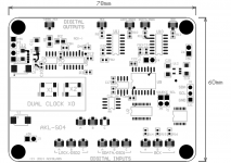
Given the type of projects going on and feedback it looks like the S03 board is very useful. A closer look at the features lately made me think that it can fit a bigger scheme of things. Most of us have already more than one I2S transport to play with and a multi-port I2S device will be very convenient. So, I have started to layout a new board (S04) that has three stereo I2S/DSD ports multiplexed into the Isolator-reclocker cct. Ports can be selected manually or I2C comms via external controller. It also interacts with compatible transports for full sync re-clocking.
As the output of the S04 goes directly to the DAC, only premium grade components are used and comes fully assembled/tested. Price-TBA
Based on this development I have also reviewed the AKU384 product and decided to adjust the design for better flexibility. It will still have all the 'lights' and whistles as per original design except the isolator and re-clocker sections are removed. This modified AKU384 can be connected directly to (wire in -U.FL connectors) one of the ports of the S04 board.
Those who have already registered their interest can still get the original AKU384 design if you still wish to and I will contact shortly to advise.
As usual, any feedback or comments welcome 🙂
Hi All,
Given the type of projects going on and feedback it looks like the S03 board is very useful. A closer look at the features lately made me think that it can fit a bigger scheme of things. Most of us have already more than one I2S transport to play with and a multi-port I2S device will be very convenient. So, I have started to layout a new board (S04) that has three stereo I2S/DSD ports multiplexed into the Isolator-reclocker cct. Ports can be selected manually or I2C comms via external controller. It also interacts with compatible transports for full sync re-clocking.
As the output of the S04 goes directly to the DAC, only premium grade components are used and comes fully assembled/tested. Price-TBA
Based on this development I have also reviewed the AKU384 product and decided to adjust the design for better flexibility. It will still have all the 'lights' and whistles as per original design except the isolator and re-clocker sections are removed. This modified AKU384 can be connected directly to (wire in -U.FL connectors) one of the ports of the S04 board.
Those who have already registered their interest can still get the original AKU384 design if you still wish to and I will contact shortly to advise.
As usual, any feedback or comments welcome 🙂
Attachments
Last edited:
S04 looks great!
Looks like a nice evolution of the S03!!!
"Assembled" including the clocks, or everything in it but the clocks so the consumer can add these?
What powers the clocks? Still going to have a choice of an external power connection for the clocks?
Isolated I2C too?
Are the A/B/C u.fls MCK?
Thanks Acko.
Looks like a nice evolution of the S03!!!
"Assembled" including the clocks, or everything in it but the clocks so the consumer can add these?
What powers the clocks? Still going to have a choice of an external power connection for the clocks?
Isolated I2C too?
Are the A/B/C u.fls MCK?
Thanks Acko.
And would this mean that you will make as "small" u.fl-output module for the amanero - to connect it to this new board?
Clocks are already mounted like in the original AKU384. 90.3168/98.304Mhz custom ultra low jitter types from either Silabs, Crystek or NDK -samples being evaluated"Assembled" including the clocks, or everything in it but the clocks so the consumer can add these?
Same as S03 with on-board or external supply optionWhat powers the clocks? Still going to have a choice of an external power connection for the clocks?
No, not necessary as it goes into a controllerIsolated I2C too?
These are divided clocks outputs (isolated) to slave the transport - 24.576/22.5792MHzAre the A/B/C u.fls MCK?
BTW, CKSEL lines were not shown, will update soon
And would this mean that you will make as "small" u.fl-output module for the amanero - to connect it to this new board?
Yes, there will be matching U.FL connectors to make it easy. Will preview shortly
Acko et al,
I'm a little confused about what is required for full synchronous re-clocking using the Acko clock module - PG7 on the App Notes.pdf. In the diagram it appears that there are two AKL-AMN boards required. On PG8 only one AKL-AMN board is shown. Is the PG8 config preferred over the PG7 config? I know that the config on PG8 requires that the Amanero firmware be flashed so that it is in slave mode. What about the setup on PG7? I'm planning on using an AKL-AMN-S02 board with the Acko Clock board. How should the CKSEL be wired up to correctly choose both XOs? Any ideas on how full synchronization should be implemented is appreciated. I'd like to eliminate the parts that I don't need on these boards and start to move forward with my project.
In the future I'll use the AKL-AMN-S03, which should provide an easier "fully synchronous" implementation, but I'm saving that for another project.
More on configuring the S03 for the Doede 1794 dac
I had a few emails with Akco on configuring the S03 for Doede's dac and thought anyone attempting this would benefit from a quick write up. I've also included a diagram of my setup. The questions in italics are mine, the boldfaced answers are Acko's.
1) The PCM1794 generates its own clock from BCK? So the MCK line from the S03 is ignored?
Yes, no external MCK is required for PCM1794
Now for the fine tuning, if you look at the "App Notes", your setup falls into the "Aysnc Mode with isolated connection and re-clocking" (Page 4).-The Pi replaces "Amanero" in this case. Pi and DAC are running on their own clocks and SO3 board has its own ref clock. With Async mode it would be preferable increase the frequency of the SO3 clock to 100MHz to reduce pulse modulation errors and you just need one XO for this case. There is also no need to use synchronous types like 98.304MHz since the operation is Async. Try mounting a CCHD575 100MHz and see how it sounds.
Later on he added this:
I indicated to you before the with your SO3-PCM DAC, the mode is Asynchronous based on your last setup. Actually, it is Synchronous drive as the PCM1794 uses the Bit Clock as it's Master Clock reference. So all good here for the best performance
2) You suggested the 100mhz CCHD575. In the FIFO thread Ian suggested the CCHD-950 (Mouser). Could you compare the two and recommend one?
CCHD575 has the lowest phase noise but if you have CHD950 100MHz, this is fine, it is not too far behind.
3) On going with a higher than 100mhz clock rate xo, since Doede's dac doesn't use MCK so you are shooting for the lower jitter and pulse modulation error which would have an effect on BCK, which is used by the dac chip to generate MCK Acko commented:
There is of course nothing stopping you from going higher ( up to 600MHz for the Potsemi chips) to see if there are further benefits so long as low jitter XOs are chosen.
4) Does it matter what position on the S03 board the single 100mhz clock goes, X1 or X2?
For single fixed XO operation, you will need to mount it on X1 position. Also make sure that R18 (near 'SEL') is mounted to act as a pull down. This will enable X1 (and disable X2).
5) About trying batteries instead of the three regulator choices Acko gives you:
Yes, you can try with batteries and see if it improves over the LTC6655 reg on-board. Also try a 6V LiFePO4 powering the reg circuit
6) I asked the following question after putting R18 in and the 100mhz clock because if I decide to try to power the clock with a LiFePO4 battery I don't want to be powering the X2 clock if I'm not using it (needless drain of the battery):
R18 takes X2 out of the circuit, so it's not powered?
Will still be powered but output disabled and in highZ.
Attachments

Acko et al,
I'm a little confused about what is required for full synchronous re-clocking using the Acko clock module - PG7 on the App Notes.pdf. In the diagram it appears that there are two AKL-AMN boards required. On PG8 only one AKL-AMN board is shown. Is the PG8 config preferred over the PG7 config? I know that the config on PG8 requires that the Amanero firmware be flashed so that it is in slave mode. What about the setup on PG7? I'm planning on using an AKL-AMN-S02 board with the Acko Clock board. How should the CKSEL be wired up to correctly choose both XOs? Any ideas on how full synchronization should be implemented is appreciated. I'd like to eliminate the parts that I don't need on these boards and start to move forward with my project.
In the future I'll use the AKL-AMN-S03, which should provide an easier "fully synchronous" implementation, but I'm saving that for another project.
The P7 config is a general concept that indicates removal of the on-board XOs of the Amanero unit (or other similar transports) and then supply equivalent isolated clocks from the AKX301 module. Of course this is a pretty invasive 'brute force' technique proposed at that time and requires an additional isolator board as shown. But since then Amanero came up with the external clock input option so the P8 config becomes neater and most recommended. So just go with P8 setup with the S01/S02 boards. The S03 board also implements the P8 concept.
Last edited:
Is this a similar situation for use with a NOS tda1541a?
Thanks
Thanks
I had a few emails with Akco on configuring the S03 for Doede's dac and thought anyone attempting this would benefit from a quick write up. I've also included a diagram of my setup. The questions in italics are mine, the boldfaced answers are Acko's.
1) The PCM1794 generates its own clock from BCK? So the MCK line from the S03 is ignored?
Yes, no external MCK is required for PCM1794
Now for the fine tuning, if you look at the "App Notes", your setup falls into the "Aysnc Mode with isolated connection and re-clocking" (Page 4).-The Pi replaces "Amanero" in this case. Pi and DAC are running on their own clocks and SO3 board has its own ref clock. With Async mode it would be preferable increase the frequency of the SO3 clock to 100MHz to reduce pulse modulation errors and you just need one XO for this case. There is also no need to use synchronous types like 98.304MHz since the operation is Async. Try mounting a CCHD575 100MHz and see how it sounds.
Later on he added this:
I indicated to you before the with your SO3-PCM DAC, the mode is Asynchronous based on your last setup. Actually, it is Synchronous drive as the PCM1794 uses the Bit Clock as it's Master Clock reference. So all good here for the best performance
2) You suggested the 100mhz CCHD575. In the FIFO thread Ian suggested the CCHD-950 (Mouser). Could you compare the two and recommend one?
CCHD575 has the lowest phase noise but if you have CHD950 100MHz, this is fine, it is not too far behind.
3) On going with a higher than 100mhz clock rate xo, since Doede's dac doesn't use MCK so you are shooting for the lower jitter and pulse modulation error which would have an effect on BCK, which is used by the dac chip to generate MCK Acko commented:
There is of course nothing stopping you from going higher ( up to 600MHz for the Potsemi chips) to see if there are further benefits so long as low jitter XOs are chosen.
4) Does it matter what position on the S03 board the single 100mhz clock goes, X1 or X2?
For single fixed XO operation, you will need to mount it on X1 position. Also make sure that R18 (near 'SEL') is mounted to act as a pull down. This will enable X1 (and disable X2).
5) About trying batteries instead of the three regulator choices Acko gives you:
Yes, you can try with batteries and see if it improves over the LTC6655 reg on-board. Also try a 6V LiFePO4 powering the reg circuit
6) I asked the following question after putting R18 in and the 100mhz clock because if I decide to try to power the clock with a LiFePO4 battery I don't want to be powering the X2 clock if I'm not using it (needless drain of the battery):
R18 takes X2 out of the circuit, so it's not powered?
Will still be powered but output disabled and in highZ.
I don't have any experience with the tda1541a, maybe Akco or someone more knowledgeable about that dac chip can comment?Is this a similar situation for use with a NOS tda1541a?
Is this a similar situation for use with a NOS tda1541a?
Thanks
Yes, this should work fine for tda1541a or other DACs
- Home
- Group Buys
- Amanero Isolator/Reclocker GB