As I know GaryB because he shared some tips about the good little Subbu V3, my understanding is this non expensive design maybe sounds better than the AYA 2 (or at least very different, but you can only listen to one dac at time and he listen to Subbu V3 today !).
From Gary's description of the power supply in his PCB it seems the newer boards from Pedja are different. For example the power supplies are not using feedback based regulators at all. Instead they common mode RC filters followed by discrete and buffered supplies (not mine to give away the information, sorry). So, hardly a direct comparison.
The core board of AYA 2, 3 will be the same. The removal of the PCM2707(9?) input for USB would be the difference. And what I'm trying to get across is to say that its the core board that you want. AYA 2 board fed via PCM (with the small mod at the chip PS to allow for this mode (its in the data sheet) using Ians full FIFO kit will sound again different from feeding the same board via I2S via CS chip with SPDIF input.
But, each to his own.
In response to your question about what I mean by 'approach', is quite simple, firstly decide that you want to use that design, get an idea of how many people would be interested, send him an email through his website asking if he would release his design to the DIY community for limited production run. Boards can have 'NON COMMERCIAL USE' screened across the top.. you then need to stop and ask - 'whats in it for Pedja?'. As you mention elsewhere - its not all about money. Exactly. Perhaps theres a local music school close by to where he is that accepts donations.
Its the though that counts, so long as you follow up on that thought if the offer is accepted.
Don't worry about negativity, but I agree wholeheartedly with the comment that you can't design an elephant by committee.. and whether you realise or not, it seems that is what you're setting up.
None of the contributors here would likely improve on Pedja's board any time soon and most of their efforts would fall short. Remember, this is his day job, this is what he does for a living - and with 1541A he's been doing it for a long time.
Other than that, arrange a home demo between Model S and DP-777 buy the one you like and write a small review. I'd read it.
Regards and best wishes,
Shane
Last edited:
...
None of the contributors here would likely improve on Pedja's board any time soon and most of their efforts would fall short. Remember, this is his day job, this is what he does for a living - and with 1541A he's been doing it for a long time.
...
Well as far as the decoupling caps, moving to SM pan films under the chip should be better right there (shorter loop, better caps) .. [To put it lightly, Thorsten's been doing it harder and for longer and his advice is more recent (Dan Brown's is more recent too)]
PS I'm not sure but did Pedja implement I2S att or DEM reclocking?
Last edited:
...
Well as far as the decoupling caps, moving to SM pan films under the chip should be better right there (shorter loop, better caps) .. [Thorsten's been doing it for longer and his advice is more recent (Dan Brown's is more recent too)]
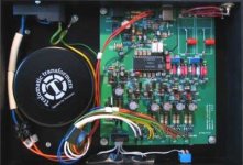
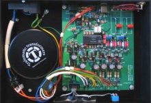
There are 14 decoupling caps, how many do you see in the photo?. About half of that. Check the pad spacing of the SMD caps WRT the tda1541A, its about 1:2. Seems pretty logical to have half above and half below, and they are indeed the very same caps that you suggest as the better alternative.
And you've missed the point - its not about who's got the bigger bladder - ask T for a PCB and see how far you get and FWIW, Dan Brown wrote the Da Vinci Code.
Anyway, I really don't feel the need to follow on with any of this; I've said all I have to say, I've offered all I have to offer.
All the best.
Last edited:
Sorry VofM, are you saying that you don't have the time to alter your PCB?
Thanks for the clarification,
Jeff
To all: Who knows Pedja the best to ask about doing another run of his PCB?
Hi AUdiolapdance,
Sorry, my bad, I missunderstood what you wrote above.
I think here we are only two as I tried before to beginn a list and nobody add its name to mine. Maybe this idea could be better with a specific thread but don't have myself the level of English to express this positiv idea to him. I didn't know the expression "to get in away"... but are able to understand your mean.
I tried but sorry here for all as I know than my reading must be difficult to understand for native of Shakespeare language. I hope just it has created a good dynamic enough even if the method was not the best.
All the best
.....So does anyone recognize what SW he used?.....
.....Does anyone recognize the design SW? Is anyone who's half decent at PCB layout gonna step up?.....
I believe it is CadSoft EAGLE PCB Design Software, usually just called "Eagle". One can get free copy (with some restrictions, no problem in this case) from CadSoft EAGLE PCB Design Software - EAGLE Support, Tutorials, Shop
There are 14 decoupling caps, how many do you see in the photo?. About half of that. Check the pad spacing of the SMD caps WRT the tda1541A, its about 1:2. Seems pretty logical to have half above and half below, and they are indeed the very same caps that you suggest as the better alternative.
And you've missed the point - its not about who's got the bigger bladder - ask T for a PCB and see how far you get and FWIW, Dan Brown wrote the Da Vinci Code.
Anyway, I really don't feel the need to follow on with any of this; I've said all I have to say, I've offered all I have to offer.
All the best.
Hey Ceglar, sorry if my post came off as snooty.
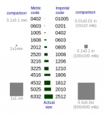
I couldn't tell from the lower res pic of the AYA if those were the new recommended Panasonic SM film caps (from Mr. Brown--what's his first name?--and Thorsten) but they are bigger than the 1210 (mounted on their side) that Thorsten recommends (they look like they're 2512?) and they are on the outside of the chip so that means longer loop area from the 1541 GND pin.
Check out VofM:
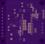
Toight!

So my logic stands, we've already done better than the AYA for these decoupling caps! No pissin', just circuit theory.
I'm not asking anyone for a PCB yet (I don't think we'll get permission from either of them, and it might be a headache to try and source their parts), just trying to get VofM's goin'
And please don't go, we need all the help we can get!
Cheers,
Jeff
Last edited:
Vanofmonks just PMed me the design files and it's in Eagle 5. (Good call new2hifi!)
Anyone good with Eagle 5? (Looks like Eagle's at 6.5 now)
Anyone good with Eagle 5? (Looks like Eagle's at 6.5 now)
Last edited:
Hi Jeff,
1206 caps.
Its all cool but what you guys are needing I don't have to offer. I don't know enough, simply know of those who do - and they're not here (open honesty).
Should be clear to most that taking what 'some people think to be the best' and combining it with 'what others consider the best' ends you up in a place with no guarantee of performance.
There is truth to the systems approach, and its nothing new. Consider everything a compromise, the net result a combination of all decisions.
The decisions need to come from comprehensive trial and error. Josh is right about the Elephant thing.. and thats the direction this is going.
The best help I can give is advice, and I'm starting to sound like a broken record on that.
Errr,... my direction is clear and has been stated many times (post 717)
http://www.diyaudio.com/forums/digi...any-good-tda1541a-dac-kit-72.html#post3882240
http://www.diyaudio.com/forums/digi...any-good-tda1541a-dac-kit-72.html#post3882240
Errr,... my direction is clear and has been stated many times (post 717)
http://www.diyaudio.com/forums/digi...any-good-tda1541a-dac-kit-72.html#post3882240
Hi,
Where can I find the values of the schematic?
Thanks.
Hi,
Where can I find the values of the schematic?
Thanks.
If VofM followed T's hints some of the values should be here:
http://www.diyaudio.com/forums/digi...-any-good-tda1541a-dac-kit-4.html#post2854098
Hey Ceglar, sorry if my post came off as snooty.
I couldn't tell from the lower res pic of the AYA if those were the new recommended Panasonic SM film caps (from Mr. Brown--what's his first name?--and Thorsten) but they are bigger than the 1210 (mounted on their side) that Thorsten recommends (they look like they're 2512?) and they are on the outside of the chip so that means longer loop area from the 1541 GND pin.
Jeff
Hi,
Do you talk about the SM caps from Cornell Dublier ? These are acrylic film. Advantage is for one Uf value you have the same effect with ESR than a 10 x greater tantale one. But as you say they are big ! I will go myself with 605 smd NPO with the 14 decoupling caps and gnd pin as they are better for RF (nothing beats Ceramic but maybe Mica... and those last are verry big for cap here). 605 smd size is for the littlier inductance than a normal DIyer could solder ! Maybe for the MSB only, i will try between X7R, the bigger SM acrylic from Cornell Dublier, radial MKT 2.5 mm space leads and radial little can polymer also with 2.5 mm leads spacing...Because the value is few uf for MSB, we can use both 603 smd NPO 0.1 uF for a low inductance at RF + the larger value with the list above !
But for design & pcb drawing (here we need holes and smd space for the MSBs...) it is flavor for the MSB!
Just a 'not have a clue about' 2 cents input 😀
Last edited:
Hi,
Do you talk about the SM caps from Cornell Dublier ? These are acrylic film. Advantage is for one Uf value you have the same effect with ESR than a 10 x greater tantale one. But as you say they are big ! I will go myself with 605 smd NPO with the 14 decoupling caps and gnd pin as they are better for RF (nothing beats Ceramic but maybe Mica... and those last are verry big for cap here). 605 smd size is for the littlier inductance than a normal DIyer could solder ! Maybe for the MSB only, i will try between X7R, the bigger SM acrylic from Cornell Dublier, radial MKT 2.5 mm space leads and radial little can polymer also with 2.5 mm leads spacing...Because the value is few uf for MSB, we can use both 603 smd NPO 0.1 uF for a low inductance at RF + the larger value with the list above !
But for design & pcb drawing (here we need holes and smd space for the MSBs...) it is flavor for the MSB!
Just a 'not have a clue about' 2 cents input 😀
I can't remember if they were Cornell Dublier (John Brown) or Pan ... I'll double check later.
I'm goin' with T's hints as summarized in post 709:
http://www.diyaudio.com/forums/digi...any-good-tda1541a-dac-kit-71.html#post3880972
DEM Decoupling
Okay, next stop, DEM Decoupling, the capacitors should be small size, surface mount and Film. There are now many such options, 0.1uF is minimum value recommended, bigger can work, but avoid physically big cap's.
For the TDA1541 ONLY we can also use these SMD film cap's for the PSU rail decoupling. At the worst it will see around 6MHz clocks AND because the TDA1541 internally uses current steering (a non-standard ECL Logic essentially), so there is much less RF in the PSU Rails we need to decouple.
I personally would add also Elna Silmic cap's on the DAC rails and use larger value film Cap's added to the MSB DEM decoupling Pins, or even Os-Con's (as for the MSB only any leakage in the cap will only change the overall level.
...and...
SMD film caps
As it stands using 1206 SMD parts for the 74HC logic in DIP format (that is parts with pins that go through the board, not SMD) will do.
For the TDA1541 use the same SMD Film Cap's for both decoupling the DEM Pins (14pcs in total) and to decouple the supply pins (3).
Using 0.1uF Panasonic types in 1210 format (stand them on edge to fit) means they are effective to around 12MHz. As the TDA1541 is bipolar current steering based, it does behave rather different from modern CMOS chips in terms of PSU noise and has no real problems with this kind of decoupling, a CMOS chip on the other hand would be a disaster area decoupled like this.
For the TDA1541 all the decoupling capacitors should be placed below the Chip pointing inwards, with a solid ground plane under the chip.
----------------------------------------------------------------------------------------------------
Again, no need to reinvent the wheel, it's all there gentlemen...
Last edited:
Hello all.
I have followed and read all the inputs and I do not think there is anything interesting on the table yet.
I would like to help you come out of this 'Super Regulator' and capacitor nightmare.
I really admire your interest and passion, and I am trying really hard to find a good platform for you guys to base your work and design on.
I found the homepage of this gentleman this evening and i believe he actually has quite a good design.
There are things that can be improved upon, but in all, I think he has done a very good job.
I have looked at his pcb, schematics, psu and - unless i have missed something - i think his design is very decent.
Before the offensive:
- No, I don't know him.
- and no, it can not outperform the cd-777, it won't even come close.
However, it is light years ahead of many of the propositions i have seen (do not even bother with the ebay crap),
and it is TDA1541 based, so:
Get to work and good luck.
* * * * * TDA1541A * * * * *
PS: You might wanna drop this gentleman a line and ask him for his permission to use his design.
Last edited:
If VofM followed T's hints some of the values should be here:
http://www.diyaudio.com/forums/digi...-any-good-tda1541a-dac-kit-4.html#post2854098
I read most of this thread, not all of it. Could not find a schematic with values of the DAC anywhere. Your link shows the DEM reclock and the I2S attenuation.
Thanks.
I agree audioLapDance, and of course: not important yet.
Yes it had always to be going to with already existing inputs and part of existing (good enough for the middle way goal fixed) designs that people would gave and putt together. But sometimes it seems harder to do than thinking about it. Evenin real with limited goal as sometimes people are helpeless as a babe... (it will be funny to try to make a space ship on a forum or designing a dac chip!). I like the americans during the second world war : they needed a car "good enough" for klimbing 45° : they designed the Jeep in 24 hours because they were a lot and eveybody came with what he knew the best... 😀
😀
Yes the SM caps are Cornell Dubliers'. It was more in fact to say that to you... as I gave up to drive a little. Just a detail for the day you will need the ref.
I personally would add also Elna Silmic cap's on the DAC rails and use larger value film Cap's added to the MSB DEM decoupling Pins, or even Os-Con's (as for the MSB only any leakage in the cap will only change the overall level.
So because of that, leakage : for MSBs' small 603 SMD + polymer is not a bad idea... I didn't see if there were holes also for the 2 or 4 MSBs ? At least for the 2 (the first on each side of the TDA....). And smaller caps with digital, Even with TDA, can not be worse because inductance. He who can do more, can do less.
But once again : that's good to see that the idea "good enough" is understood... Keeping the Vano pcb is a good idea either. Maybe a V15 could work and futur revisions after a first working one improve the initial design... like with others famous DIY.
Ok Audiolapdance, you are pragmatic... let's glue to Vanofonk concret pcb & T Loesch inputs... better idea than "redesign with best of breeds" I hoped like we do in IT when CEO don't want to go with SAP... When a need then a solution ! (from Prometheus famous book: "have you Light, please" )
Hé it's comming along little by little...
Yes it had always to be going to with already existing inputs and part of existing (good enough for the middle way goal fixed) designs that people would gave and putt together. But sometimes it seems harder to do than thinking about it. Evenin real with limited goal as sometimes people are helpeless as a babe... (it will be funny to try to make a space ship on a forum or designing a dac chip!). I like the americans during the second world war : they needed a car "good enough" for klimbing 45° : they designed the Jeep in 24 hours because they were a lot and eveybody came with what he knew the best...
 😀
😀 Yes the SM caps are Cornell Dubliers'. It was more in fact to say that to you... as I gave up to drive a little. Just a detail for the day you will need the ref.
I personally would add also Elna Silmic cap's on the DAC rails and use larger value film Cap's added to the MSB DEM decoupling Pins, or even Os-Con's (as for the MSB only any leakage in the cap will only change the overall level.
So because of that, leakage : for MSBs' small 603 SMD + polymer is not a bad idea... I didn't see if there were holes also for the 2 or 4 MSBs ? At least for the 2 (the first on each side of the TDA....). And smaller caps with digital, Even with TDA, can not be worse because inductance. He who can do more, can do less.
But once again : that's good to see that the idea "good enough" is understood... Keeping the Vano pcb is a good idea either. Maybe a V15 could work and futur revisions after a first working one improve the initial design... like with others famous DIY.
Ok Audiolapdance, you are pragmatic... let's glue to Vanofonk concret pcb & T Loesch inputs... better idea than "redesign with best of breeds" I hoped like we do in IT when CEO don't want to go with SAP... When a need then a solution ! (from Prometheus famous book: "have you Light, please" )
Hé it's comming along little by little...
…
I found the homepage of this gentleman this evening and i believe he actually has quite a good design.
…
- No, I don't know him.
…
Hi Alexiss,
I corresponded with this fellow a while ago on an Israeli forum. He also participated in the past in the forums here.
As far as I remember, he never actually built this DAC. He said he is interested in gathering schematics, more than in actually building.
Thus, the schematic he published may have some benefits, yet the PCB is yet to be ordered and the assembled DAC to be tested. Indeed, there is a potential for it being better that the currently available PCB's and kits on eBay, yet, it is to be tested, as "the proof of the pudding is by eating it".
...
PS: You might wanna drop this gentleman a line and ask him for his permission to use his design.
Already did a week ago and no response yet ...
I concur that it's a good design ...
Excellent information Mr. Joshua_G. Thank you.
Well, the fact that the Dac design (pcb in particular) has not been built and
tested makes things difficult....
This is a very important info, thanks again.
I want to help the guys here find a good platform with relevant (technical),
and most importantly good "implementational" information of a fairly good TDA1541 based Dac.
Concentrating on things that are influential to the final sonic performance of the TDA1541 chip.
As many of you may have noticed, there is a disproportionate focus - on proportionately less relevant issues.
In any design (thanks to vanofmonk for sharing his work), discussing the choices
of passive peripheral circuitry is one of the last open issues on the agenda. It should not be the first.
I have looked a little more on the schematics provided by this gentleman (thanks) and I think he has gathered
many of the sonically important issues in the design of a TDA1541 based dac.
Yes, his PCB design, can be improved upon, but it shows pictures of the implementation
(component placement, capacitor size and placement, orientation of the components, use of GND plane etc)
so that people get the chance to actually "see" what the arrangement looks like.
One of the important issues is the psu solution in his proposal, based on Mr Nazar's very comprehensive
homepage.
I think this is a very good start.
For all to remember:
Implementation is everything.
Mr. Loesch has tried numerously to get this point across:
Using a first-Rate chip (Regulator) in a sub-optimal "arrangement" will give a much worse results than a fully optimized LM7xxx chip.
Pay closer attention to his recommendations (Mr. Loesch), they are quite valuable.
Remember: Regulator Output Noise is measured by manufacturers under circuimstances quite different from how they are
used in an actual design.
Many of you recommended LDO Regulators, these are imho not very optimized for Audio. Getting good performance from these
are not as easy as one might assume.
When reading the comments of the contributors here, as wonderfully enthusiastic as they are,
I feel that some propositions are put forward with less consideration and more "hope".
Take a look at his design and discuss the implementation among yourselves. I think it may be positive.
Good luck
Last edited:
...
As far as I remember, he never actually built this DAC. He said he is interested in gathering schematics, more than in actually building.
Thus, the schematic he published may have some benefits, yet the PCB is yet to be ordered and the assembled DAC to be tested. ...
Ya, I picked up on that just from the website. Many of the pics are just 3-d layout drawings and the one real 'pic' doesn't have anything soldered ...

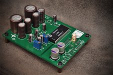
But the real PCB implies he had at least one made ...
- Status
- Not open for further replies.
- Home
- Source & Line
- Digital Line Level
- Any good TDA1541A DAC kit?