SMPS2000R version A Test
Finally found the time to test SMPS2000R from Connex electronics.
All test images performed at +/-63 V on 4 Ohm load, meaning 15 A constant output current.
There are two different versions Cristi sent to me. This test is performed with version A which has 2 x 5000 uF/100 V in secondary capacitor bank.
Images:
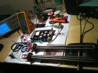
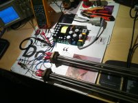
1. SMPS2000R version A test rig
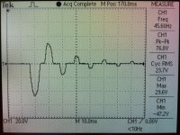
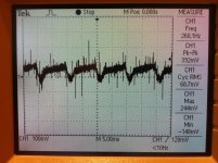
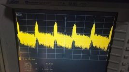
2. Mains inrush current at first few half periods going in order: 47,2 Ap, 29,6 Ap, 16,4 Ap, 11,8 Ap, 7,2 Ap etc. When NTC relay kicks-in, inrush current never exceeds 5 Ap, so relay just takes care that primary capacitor bank charges without any serial resistance.
Primary capacitor bank is formed by four 470 uF/400 V Nichicon caps in both versions and stores app. 90 J of energy, so for 10 ms period it can serve with staggering 9 kW power pulse.
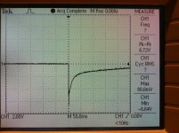
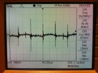
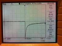
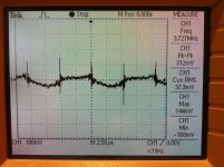
3. positive rail 6 V voltage drop at 15 A loading
4. positive rail low frequency ripple at 15 A loading
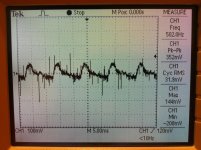
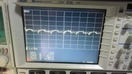
5. positive rail high frequency ripple at 15 A loading
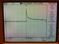
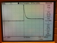
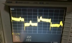
6. negative rail 6 V voltage drop at 15 A loading
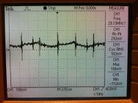
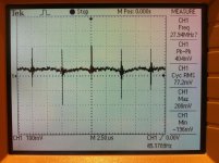
7. negative rail low frequency ripple at 15 A loading
8. negative rail high frequency ripple at 15 A loading
Finally found the time to test SMPS2000R from Connex electronics.
All test images performed at +/-63 V on 4 Ohm load, meaning 15 A constant output current.
There are two different versions Cristi sent to me. This test is performed with version A which has 2 x 5000 uF/100 V in secondary capacitor bank.
Images:
1. SMPS2000R version A test rig
2. Mains inrush current at first few half periods going in order: 47,2 Ap, 29,6 Ap, 16,4 Ap, 11,8 Ap, 7,2 Ap etc. When NTC relay kicks-in, inrush current never exceeds 5 Ap, so relay just takes care that primary capacitor bank charges without any serial resistance.
Primary capacitor bank is formed by four 470 uF/400 V Nichicon caps in both versions and stores app. 90 J of energy, so for 10 ms period it can serve with staggering 9 kW power pulse.
3. positive rail 6 V voltage drop at 15 A loading
4. positive rail low frequency ripple at 15 A loading
5. positive rail high frequency ripple at 15 A loading
6. negative rail 6 V voltage drop at 15 A loading
7. negative rail low frequency ripple at 15 A loading
8. negative rail high frequency ripple at 15 A loading
Attachments

SMPS2000R version B Test
All test images performed at +/-63 V on 4 Ohm load, meaning 15 A constant output current.
There are two different versions Cristi sent to me. This test is performed with version A which has 2 x 2800 uF/100 V in secondary capacitor bank.
Images:
1. SMPS2000R version B test rig
2. Mains inrush current at first few half periods going in order: 47,2 Ap, 29,6 Ap, 16,4 Ap, 11,8 Ap, 7,2 Ap etc. When NTC relay kicks-in, inrush current never exceeds 5 Ap, so relay just takes care that primary capacitor bank charges without any serial resistance.
Primary capacitor bank is formed by four 470 uF/400 V Nichicon caps in both versions and stores app. 90 J of energy, so for 10 ms period it can serve with staggering 9 kW power pulse.
3. positive rail 8 V voltage drop at 15 A loading
4. positive rail low frequency ripple at 15 A loading
5. positive rail high frequency ripple at 15 A loading
6. negative rail 8 V voltage drop at 15 A loading
7. negative rail low frequency ripple at 15 A loading
8. negative rail high frequency ripple at 15 A loading
Attachments


Not bad  , and will be further improved with burning time, i suppose.
I'm curious to see the comparison with the others... and how it sound.
, and will be further improved with burning time, i suppose.I'm curious to see the comparison with the others... and how it sound.
Last edited:
SMPS2000R + First One
SMPS2000R is just too powerful to supply only one First One amplifier module, so it is ideal for powering stereo version. Also some members prefers one single PSU for both channels as for better stereo imaging coming from one single ground layout.
At 15 A constant loading there is only 2 V DC voltage drop on both rails, so from power reserve point of view one SMPS2000R is sufficient for supplying two channels.
Test with First One stereo amplifier coming soon. 😎
Thanks Cristi.
Regards L.C.
BTW, i don't know for this one, but i used some other Connex SMPS on a class D amp and had the best results in setting the PSU in a Faraday cage + short and strait power wires.Test with First One stereo amplifier coming soon.
My two cents, just in case.
Oh, and, may-be it would be interesting to look at what happens near the AC line, don't you think ?
Last edited:
Hi,
Thanks for the measures, LC.
Watch me as passionate or Engineer, please not as competitors.
I have huge difficulties to participate in the interpretation of these measures, of course, are "first measure,right electric side", I mean, others need very important in the case of audio amplifier.
The initial opinion of Esperado, confirmed by LC, tells me that it is a conflict if I examine these simple measure with my knowledge.
But if we do not discuss in interpreting the measure, understand what others?
Regards
Last edited:
AP2, those electrical measures just show if this (or any other) SMPS pass the basic requirements. If it was not the case, no need to spend more time to listen to it, right ?The initial opinion of Esperado, confirmed by LC, tells me that it is a conflict if I examine these simple measure with my knowledge.
But if we do not discuss in interpreting the measure, understand what others
Looking at this first step, it "Passed". Right ? I presume your will be the same.
You can expect from LC. to dig further in the only interesting thing: How it sound in the "First one" context. And there is too many influences of the various imperfections that all SMPS (and his own amp) carry to satisfy ourselves on pure electrical measurements.
On my side, i'm very interested, as an example, to can figure out how behave regulation VS no regulation, on a sonic point of view and a very sensitive CFA amplifier.
And, outside of any commercial point of view, and because L.C. is both a clever audio designer and a very sensible 'listener', we will all learn something from this confrontation.
Last edited:
Hi,
Thanks for the measures, LC.
Watch me as passionate or Engineer, please not as competitors.
I have huge difficulties to participate in the interpretation of these measures, of course, are "first measure,right electric side", I mean, others need very important in the case of audio amplifier.
The initial opinion of Esperado, confirmed by LC, tells me that it is a conflict if I examine these simple measure with my knowledge.
But if we do not discuss in interpreting the measure, understand what others?
Regards
Hi AP2
These are just intial mesurements before connecting any amp channel, just to be sure the SMPS is giving the power it is specified and shows what are the ripple conditions on resistive load at rated output current.
Dynamic rails conditions at bursts of AC loading current when amp is connected will follow later.
Regards L.C. 😉
P.S. In my opinion DC and ripple responses at 15 A constant output current are quite impressive, don't you think?
Last edited:
AP2, those electrical measures just show if this (or any other) SMPS pass the basic requirements. If it was not the case, no need to spend more time to listen to it, right ?
Looking at this first step, it "Passed". Right ? I presume your will be the same.
You can expect from LC. to dig further in the only interesting thing: How it sound in the "First one" context. And there is too many influences of the various imperfections that all SMPS (and his own amp) carry to satisfy ourselves on pure electrical measurements.
On my side, i'm very interested, as an example, to can figure out how behave regulation VS no regulation, on a sonic point of view and a very sensitive CFA amplifier.
And, outside of any commercial point of view, and because L.C. is both a clever audio designer and a very sensible 'listener', we will all learn something from this confrontation.
We can not rely entirely on the current and voltage, but in behavior during the current delivery. in this phase we analyze a lot of parameters, in accordance with the operation of an amplifier.
without it, all are good and very simple smps develop, simply abound with the filter capacitors.
I expect other types of measures (I'm sure LC will) to see if any problems have been resolved.
This implies that we know what are the "problems". if we do not agree on this, in the end, the difference will be.... "DPS-500 you have to buy two, one x amps, the connex is sufficient one".
Experado, if I decided to send the samples at Andej, it is only because he has good ears. a good brain, and I want him, listen to a new sound performance. the commercial reasons are secondary.
L.C. My previous post asked, we can interpret the measurements? from a purely technical point of view, certainly for the benefit of others.
Last edited:
Look at them: You can have an idea of the ripple, both at low and high frequency, and how it behave (speed of regulation) at a simple full current loading instant. *Very good*, with no doubt.L.C. My previous post asked, we can interpret the measurements? from a purely technical point of view, certainly for the benefit of others.
Of course an amp with various musical transients will present a lot more complex landscape.
On an human point of view, I'm sure, both of you are very similar, and have a very special (to keep-it soft) character ;-)
Both passionated engineers, proud of their products, more interested in your work than in business. And, i hope, better in electronic design than in communication ;-)
You could be good friends if both of you had the occasion to meet you without preconceived idea about the other. May-be the occasion to exchange friendly for the benefit of both of you ?
.
LC: thank you for the detailed measurements.
I have some suggestions:
Please make the measurements from 3. and 6. using 150-200mA initial current.
The SMPS2000R is designed to run in burst mode at low load or no load. during burst mode the power stage delivers burst of pulses for few ms then stop switching for 50-500ms to keep the output voltage constant. if a high current is drawn while the power stage is not switching the ouptut voltage will drop considerably. It is well know and desired feature. with 200mA initial load and 10A pulses the undershot is much lower, I measured 145mV only. every audio amplifier has a quiescent current of at least 20mA for each 100W output power. The SMPS2000R is capable to supply class D amplifiers with output power of at least 2000W or class AB amps with at least 1200W-1500W. any of these amps will draw at least 200mA quiescent current which will bring the SMPS2000R in normal operation instead of burst mode. in the SMPS2000R manual, page 6 is a table with min load values for non-burst mode operation.
Connect the scope probes without the ground wire for an acurate measurement of the ripple: Understanding, Measuring, and Reducing Output Voltage Ripple - Simple Switchers Wiki - SIMPLE SWITCHER® - TI E2E Community
Use an EMI filter such as the one used when I measured the conducted emissions: CW4L2-20A-T for an accurate test and one ferrite bead on output wires. details in manual: http://www.connexelectronic.com/documents/SMPS2000R.pdf
Esperado:
Shielding the SMPS will reduce the radiated noise furthermore, but it must be done carefully otherwise will make it worst. due to the topology used, the highest intensity of the radiated field is nearby transformer. I suggest placing the amplifier modules and sensitive wiring at distance of at least 15cm away and parallet with the board to minimize any possible noise pick-up instead of shielding the power supply. In any case I do not suggest to shield the transformer, neither with ferrous or non-ferrous shields.
Below are some measurements which I made on a +-60V unit. each picture has the description of the measurement. The measurements are done with the scope sensitivity of 20 and 50mV probe attenuation 1:1.
Attachments

Experado, if I decided to send the samples at Andej, it is only because he has good ears. a good brain, and I want him, listen to a new sound performance. the commercial reasons are secondary.
I thought you've sent them already by now. 🙁
Esperado:
If we apply a resistive load, then continuous, the work of the error amplifier is limited to the modular inverse, the PWM at a frequency of 100Hz in this case. large filtering capacitors slow (help) this modulation.
The ripple at low frequency (100Hz) has never been a problem in professional amps for amateurs, we also have up to 5 voltVp (on 70V). in linear psu. but even in this case, it is important to see "when" voltage drop, in relation to the current demand.
We need the audio transient, to see how long it takes to err amp react.
Maybe this will see later.
For now, I see two things that are not good but the fact that you have not seen, puts me in trouble. For this reason, I have asked if they can comment on the measures. 😉
Last edited:
I thought you've sent them already by now. 🙁
Yes, but you know my english is perfect. 🙂
To me, measures are somewhat important, unless you have to deal with computers and other precision equipment... This is sound and as such, it is the end result that gets to my ears that matter. Some things can be seen on a scope but won't change the end results in the audible human ear perception so I'm not worried about all this. What I want to read is LC's sound test with the amplifiers.
Ciao!
Do
Ciao!
Do
Esperado:
If we apply a resistive load, then continuous, the work of the error amplifier is limited to the modular inverse, the PWM at a frequency of 100Hz in this case. large filtering capacitors slow (help) this modulation.
The ripple at low frequency (100Hz) has never been a problem in professional amps for amateurs, we also have up to 5 voltVp (on 70V). in linear psu. but even in this case, it is important to see "when" voltage drop, in relation to the current demand.
We need the audio transient, to see how long it takes to err amp react.
Maybe this will see you later.
For now, I see two things that are not good but the fact that you have not seen, puts me in trouble. For this reason, I have asked if they can comment on the measures. 😉
What you are asking is shown in the first picture: Step load 200mA to 10A 12-13ms.
Have you made the measurements which I asked few days ago ? I didn't saw the result yet.
I'm not sure why you always mention about PWM even when you refer to SMPS2000R. Try to understand that I'm not using PWM, but more newer and efficient topology.
Hi,What you are asking is shown in the first picture: Step load 200mA to 10A 12-13ms.
Have you made the measurements which I asked few days ago ? I didn't saw the result yet.
I'm not sure why you always mention about PWM even when you refer to SMPS2000R. Try to understand that I'm not using PWM, but more newer and efficient topology.
What do you want see in so far you suggested, is already visible in the measurements that I put on the thread. however, the LC will.
Sorry if I call "PWM" (Pulse Wide Modulation), somewhere, will have a "error amplifier", I meant that.
Pinnocchio: I agree in part with what you say, becouse we can not rely entirely on the experience of the listener, the risk as you know, is that it can say "amazzing sound" simply because they do not know where the problem reflects the smps. but if you present your smps to an engineer, professional amps, he knows what to look for in the measurements. when listen, him feels where the problem is. often refuses to listen in more cases.
So serious measures, are sacred. ...later, with the words you can do everything.
I hope that this competition can be of great help to all lovers of good music, just those who not have the necessary experience in smps.
Last edited:
In the final realization, it was a massive aluminum case separated in two volumes by a thick separation machined in the mass. Two covers, one for the PSU, one for the amps, screwed in the aluminium, isolated from each other. Lot of air around your SMPS but less than 15cm.Shielding the SMPS will reduce the radiated noise furthermore, but it must be done carefully otherwise will make it worst.
Yes, local deliveries only, soon after the others will follow. 😉so LC did you start sending the first orders?
Mundorf caps from Germany arrived just yesterday, will post some pics tomorrow. 😎
- Home
- Vendor's Bazaar
- First One - mosFET amplifier module