the current in the upper half is the same as the current in the lower half, because the load is disconnected.
If you are reading 470mVrs and 430mVrs, then there is something wrong with your methodology, the currents cannot be different.
Did you select your Source Resistors?
If you are reading 470mVrs and 430mVrs, then there is something wrong with your methodology, the currents cannot be different.
Did you select your Source Resistors?
I 'm measuring the voltage across the 1 ohm resistors. I have a few digital meters so I'm measuring the N and P sides at the same time. I have shorted the input, but I have also (and I guess that's where the problem is, based on your post) strapped an 8 ohms 20 W resistor across the speaker output terminals. Do you think think that's the issue?
I'll take it off when I get home and retest my voltages.
Thanks for the input AndrewT.
I'll take it off when I get home and retest my voltages.
Thanks for the input AndrewT.
If you are reading zero DC offset then you will be OK.
I set the bias with no load attached. That may be the culprit, however you mention that your Mosfets are unmatched, you may be reading across one that is current hogging.
Also you mention that your Mosfet are at 75C. Reduce bias until they are stable at 65C.
I set the bias with no load attached. That may be the culprit, however you mention that your Mosfets are unmatched, you may be reading across one that is current hogging.
Also you mention that your Mosfet are at 75C. Reduce bias until they are stable at 65C.
Thanks. I measured the voltages without a load. It made no difference. Then rather than always measuring the same Mosfet on each rail (TP 3 and 4 on the PCB bought from this site), I measured the other Mosfet's current, to check for a current hog as you suggested.
You were right, because they're unmatched, one Mosfet draws more current than the other. I expect the sum of the currents on the N side equals the sum on the P side. I guess I should match them if I don't want one Mosfet to get way hotter than the rest. (I'll measure the temp, if it's not different I might to just forget about it).
As an interesting aside, as I'd turned the bias pretty high up, and the diodes hadn't kicked in, I was beginning to wonder if they ever would...They eventually did in spectacular fashion: As I was trouble shooting my bias problem, I decided to add a 3 W 10 Ohms to the 1 ohm resistors on the N side. It did correct the bias problem in the right direction. In the various changes I was making, I once had the bias turned too high, and the variac turned all the way up when I flicked it on. The 10 Ohm resistor burst into flames ! No wonder the manual says you may want to have a fire extinguisher! Luckily nothing else was affected, so all's good.
Last edited:
setting up F5
The input must be fitted with a dummy load. This ensures there is NO DC voltage applied to the input.
The output load MUST be disconnected.
The input must be fitted with a dummy load. This ensures there is NO DC voltage applied to the input.
The output load MUST be disconnected.
Power Supply PCB
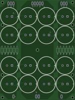
Hi does anybody know where to buy pcb for 16 x 10000 uf 50 V 30 mm Ø ? Just bought 32 ROE 105 celcius from Vilnius .
Hi does anybody know where to buy pcb for 16 x 10000 uf 50 V 30 mm Ø ? Just bought 32 ROE 105 celcius from Vilnius .
Bolt or glue the capacitors to the chassis.
Hard wire the pins.
Ensure the loop areas of the hard wiring are minimised.
I use clear silicone window sealer as a glue.
Sometimes to the floor of the chassis, sometimes to the side panel, even to the back panel, if that suits the layout of the other components.
Hard wire the pins.
Ensure the loop areas of the hard wiring are minimised.
I use clear silicone window sealer as a glue.
Sometimes to the floor of the chassis, sometimes to the side panel, even to the back panel, if that suits the layout of the other components.
Bolt or glue the capacitors to the chassis.
Hard wire the pins.
Ensure the loop areas of the hard wiring are minimised.
I use clear silicone window sealer as a glue.
Sometimes to the floor of the chassis, sometimes to the side panel, even to the back panel, if that suits the layout of the other components.
Hehe Andrew thats what I usally do. Wanted it to look more professionel this time.
Another thing is I wonder why it use those CRC. 0,07 ohm does not improve anything in my world ?
Hi does anybody know where to buy pcb for 16 x 10000 uf 50 V 30 mm Ø ? Just bought 32 ROE 105 celcius from Vilnius .
I have made this layout to another project, but you get the gerber and send to seeedstudio if you like. Board is 150x200 mm and snap-ins are 35 mm Ø. I have made it single sided because I plan on etching it myself when I get around to it. 😀
Attachments
I have made this layout to another project, but you get the gerber and send to seeedstudio if you like. Board is 150x200 mm and snap-ins are 35 mm Ø. I have made it single sided because I plan on etching it myself when I get around to it. 😀
Thanks I can etch it it to. I have all what I need. Some years since i used it .
How big are the loop areas?
Have you taken any steps to reduce emi?
Feel free to elaborate about your concern. The layout is very simple - basically just 5 cobber bars like it is often done with screw mount capacitors (see e.g. Pass Labs' larger models).
The loop area in between the flow and return traces will emit interference.
If you have a two layer board you can superimpose the flow and return one above the other.
A single layer board should keep the flow and return traces close together.
If you have a two layer board you can superimpose the flow and return one above the other.
A single layer board should keep the flow and return traces close together.
So basically, identical challenges as seen in p2p mounting. 😉
I'm more concerned about the fields from the transformers and I am also considering using four 2mH air-coils for CLC. It is difficult to find a way to place them without having magnetic fields all over the place.
I'm more concerned about the fields from the transformers and I am also considering using four 2mH air-coils for CLC. It is difficult to find a way to place them without having magnetic fields all over the place.
I am making live measurements of a balanced 1/2 Turbo. By 1/2 Turbo I mean it has one MOSFET per rail and one MUR1510 diode per FET. Here is an image of the board and is attachment to 1/2 of a HeatsinkUSA 10.08" x 7" heatsink:
Did you come to any personal conclusion?
My observations were if using a diode in parallel with a resistor the sweet spot was 3 to 4 times the current through the diode with respect to the resistor. When biased at 1.3A
eg 1A through diode and 300mA through resistor. This combo gave better distortion figures at virtually all power levels not just at high power.
In the end it was a bit of messing around to get the right resistance value to meet this 4 to 1 ratio so I just did away with the resistor and biased the circuit up using just a diode at the source of the mosfet.
I still haven't had a chance to properly compare the thing to my other amps. Bloody slow
I should get to it soon though.
Sorry to change subject but just wondering.. What would happen if I used 24v to power F5 turbo..? As a temp solution
- Status
- Not open for further replies.
- Home
- Amplifiers
- Pass Labs
- F5 Turbo is posted