We all try this, John. The thing is that, comparing the same musical signal in the input of VAS, we see a very different landscape (whatever some pretend) when we change the charge of an amp from a resistance to a real speaker. This is something i experiment since decades.MY solution to IIM is to have the LOWEST open loop impedance possible, so that the output stage itself tends to absorb the speaker current directly and almost instantly, using feedback just to lower output Z further. This way, the input stage is less stressed trying to keep the amp output at the proper voltage.
Er.rrh! You still haven't told us what advantages Diamond i/p gives over Simple CFA.
I've already mentioned the caps. You may like to look back on some of my previous posts with examples of Simple CFA for circuits and compare complexity.
And in your list of Krell ... Cyrus, there are several which are unstable into 'real life' speakers .. though I'm not sure CFA has anything to do with this.
And I DID say, 1nV/rtHz isn't for everyone but you may like to work out what you really need for your zillion bit D/As
______________
Andrew (Bonsai), I'm really just making sure we keep Simple CFA on the table (and yanking your chain a little).
I was disappointed to hear of your troubles with nx-amp 😡 but if I build a CFA, it will likely be one of your excellent designs. 'Tried & tested' beats theoretical flights of fancy any day.
I'm re-thinking my 'favourite' amp topology because of shortcomings in areas which are nothing to do with 1ppzillion THD or zillion V/us slew. To really move forward, it's important to question all previously held beliefs & prejudices and concentrate on very basic & crude parameters which have been checked with Double Blind Listening Tests. 🙂
The chosen topology/design should address these issues .. not the other way round. 😀
😱 Could you point out which of those oscillates, I personally have had a hand in some of those, pray its not one of mine but I highly doubt it. Final designed products are rigorously tested for a couple of months before going into full production. Certification and Quality assurance is obtained after that.
I thought that was answered, no caps required. Other benefits are not of relevance when it comes to audio power amps. Now you may say that the caps are not required by adding this or that circuitry but thats exactly where what was once simple becomes even more complex than a diamond. About capacitor (electrolytic) linearity nothing needs to be said, they suck.
I'm not sure of this. (Not at all)
A loudspeaker is too a generator (a microphone), continue to resonate and move after the original signal has ended, and send this signal to the speaker's terminals -> feedback. And even if there is no signal at the source, noises in the room will produce a signal in this feedback path, héhé.
A power amplifier driving a load delivering its own voltage (by a back-EMF or microphonic effects) is nothing else than a closed circuit consisting of two voltage sources connected together through a series of complex impedances (output impedance of the amp, connectors, cables, crossovers, impedance of the driver).
To study effects of a voltage source as a load for an amp on the negative feedback behaviour of this amp, just drive the amp input with a null voltage and connect its output to whatever you think it can encounter in the real world.
This "whatever" can be another power amp in series with a complex impedance mimicing the driver and its associated passive components.
The whole can be easily modeled.
Were is the misbehaviour of the amp ?
I have yet to encounter proofs of bad effects from electrodynamic loudspeakers considered as voltage sources (in series with a significant impedance, do not forget) on standard amps (CFA or VFA does not matter).
Oh yes ? Please, do the following. Record on two time coded tracks the output of your favorite amp, charged with resistance. And again, on two other tracks, same time code, same amp, this time charged with your favorite speaker.why do you apparently disregard feedback theory well established > 1/2 a century ago, or the ~1980's Cherry, Cordell's JAES papers on "interface intermodulation distortion" as one of the guru's back then was trying to brand this nonissue
Compare instant with good headphones.
We all try this, John. The thing is that, comparing the same musical signal in the input of VAS, we see a very different landscape (whatever some pretend) when we change the charge of an amp from a resistance to a real speaker. This is something i experiment since decades.
that happens to be feedback actually doing some work - as expected
see Cherry's last JAES paper “Estimates of Nonlinear Distortion in Feedback Amplifiers” JAES V48#4 2000
Oh yes ? Please, do the following. Record on two time coded tracks the output of your favorite amp, charged with resistance. And again, on two other tracks, same time code, same amp, this time charged with your favorite speaker.
Compare instant with good headphones.
did you use amps carefully designed at least Self's, Cordell's books - attending to the routing, common impedance, feedback pickoff point... ie deal with all the well documented by now real world ways to fail?
use high loop gain feedback as pithily explained by Putzeys feedback article "The F-word or, why there is no such thing as to much feedback"
"flat, wide band open loop", low feedback, "simple" amps can have 10-100s of milliohm of Z externally visible from output active devices modulating gm, hfe, and have less PSRR, all worse than higher loop gain, 2-pole compensated global negative feedback amps with the same outputs (but way more loop gain applied to control the outputs)
then wiring and output decoupling inductor add more 10s-100s of milliohms Z - many don't use best implementation of the series inductor...
Last edited:
Since you are on the feedback concept right now what effect would there be by adding a third wire to the loudspeaker at the speaker terminal, after any cabling and used this as the NFB source point? This would seem to include everything possible into the feedback loop and would be your comparator point, complete global feedback.
This was tried in a sense by Valodyne except they use an accelerometer in servo with an amplifier.
davada,
I am aware of the servo controlled speakers, that is not what I was looking for. That is a speaker control issue attempting to limit the speaker distortion and not a global feedback loop only related to the amplifier signal and any interaction with the back emf of a speaker.
I am aware of the servo controlled speakers, that is not what I was looking for. That is a speaker control issue attempting to limit the speaker distortion and not a global feedback loop only related to the amplifier signal and any interaction with the back emf of a speaker.
MiiB, you are on the right track. IIM is real. Feedback is what you say it is. MY solution to IIM is to have the LOWEST open loop impedance possible, so that the output stage itself tends to absorb the speaker current directly and almost instantly, using feedback just to lower output Z further. This way, the input stage is less stressed trying to keep the amp output at the proper voltage.
Hi John,
IIM IS real. Nobody is denying that. Only a fool would think that injecting a signal current into the output of an amplifier that has a forward signal would not result in IM between the two signals (forward and backward).
Indeed, the output impedance of ANY real-world amplifier is nonlinear, whether that amplifier employs NFB or not. This nonlinearity alone will result in IIM if a significant current is back-injected into the amplifier.
The thing that many do not understand is that NFB is not the bad guy here (as long as it is properly designed and the amplifier has plenty of drive current margin).
Just as with his erroneous claims that wide open-loop bandwidth was necessary for low TIM, so Otala was also wrong in asserting that low open-loop output impedance was necessary for low IIM.
That having been said, for a given amount of NFB loop gain, a lower open-loop output impedance makes things better. The best way to achieve such lower open-loop output impedance is to have more current gain in the output stage, as with a Triple output stage rather than just a double. Conversely, a mis-guided designer who simply lowers open-loop output impedance by loading the VAS with a shunt resistor does not improve things at all - and usually makes them worse.
The closed-loop output impedance is what is more important. If you think about it, the amount of back-feed voltage that makes its way back to the input and "stresses" the input stage is the same, as long as the closed loop output impedance is the same, whether that closed loop output impedance is achieved by high feedback or low open-loop output impedance.
Cheers,
Bob
How is the open-loop output impedance lowered by loading the VAS? Please explain.
Wouldn't this lead to a rise in distortion?
davada,
I am aware of the servo controlled speakers, that is not what I was looking for. That is a speaker control issue attempting to limit the speaker distortion and not a global feedback loop only related to the amplifier signal and any interaction with the back emf of a speaker.
Would a second coil on the former of the speaker feeding back to the amplifier be more inline with you suggestion?
How is the open-loop output impedance lowered by loading the VAS? Please explain.
Wouldn't this lead to a rise in distortion?
Yes, it will generally lead to a rise in distortion. That's why it is not a good idea.
Loading the VAS with a resistor will lower its output impedance (for now let's ignore the frequency-dependent lowering of the VAS output impedance due to Miller compensation). The open-loop output impedance of the amplifier will then be reduced because it is roughly the output impedance of the VAS divided by the current gain of the output stage.
Cheers,
Bob
So if the output stage current gain is about equal to the VAS open loop output impedance then open-loop output Z would be about 1 ohm. Further more the the high current gain of the output stage decouples the VAS from the output. I think this is your case.
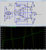
interaction of the out stage and speaker system
Class A (60W, 8 ohm)
 [/URL][/IMG]
![URL]](/community/proxy.php?image=http%3A%2F%2F%5BURL%3Dhttp%3A%2F%2Fwww.radikal.ru%5D%5BIMGDEAD%5Dhttps%3A%2F%2Fs019.radikal.ru%2Fi626%2F1404%2Fca%2F8b443be5df78.png%5B%2FIMGDEAD%5D%5B%2FURL%5D&hash=bd17732c0d6c1d17ffeea0d74b06deda)
Class AB (120W, 4 ohm)
![URL]](/community/proxy.php?image=http%3A%2F%2F%5BURL%3Dhttp%3A%2F%2Fwww.radikal.ru%5D%5BIMGDEAD%5Dhttps%3A%2F%2Fs019.radikal.ru%2Fi617%2F1404%2Fe6%2Fe270deb40904.png%5B%2FIMGDEAD%5D%5B%2FURL%5D&hash=f94cf1302022dab4f7a6c1180822a790)
 [/URL][/IMG]
no comment
best regards
Petr
Class A (60W, 8 ohm)
Class AB (120W, 4 ohm)
no comment
best regards
Petr
It's not really necessary to use input signal in the simulation. I did some test, without input signal, but with back emf signal from the output. There are very "nice" signals are present in the feedbacked amplifiers. Sometimes the VAS working very hard to keep the output 0 voltage..
Sajti
Sajti
There is another solution to avoid the back emf signal from the feedback loop. Using separate voltage amplifier with individual feedback, and output buffer with individual feedback. This means that the back emf has no influence for the low level input signal.
Sajti
Sajti
sajti (5576)
There is another solution to avoid the back emf signal from the feedback loop. Using separate voltage amplifier with individual feedback, and output buffer with individual feedback. This means that the back emf has no influence for the low level input signal.
You're right, there's an option
 [/IMG]
best regards
Petr
There is another solution to avoid the back emf signal from the feedback loop. Using separate voltage amplifier with individual feedback, and output buffer with individual feedback. This means that the back emf has no influence for the low level input signal.
You're right, there's an option
best regards
Petr
or you could just go with competent example amps like Bob's 1982 EC MOSFET AMP
add realistic 2 uH series L, soften "back EMF" square wave edges to 1A/100uS
my sim gives 10 uV "IID" step size with 1 A injected trapezoid across 8 Ohms load
the trapezoid is still a bit rich in unrealistic ultrasonic harmonics for anything speaker nonlinearities are likely to produce so the sim has 50 uV microsecond time scale spikes at the output - divide by 20x feedback network ratio for a whopping 5 uV transient error at the input
there could be a reason so many in this thread think there's lots of "moving parts" to "amplifier sound" - because they design/listen to amps with poor control (and poor controls)
"just build" coupled with "just listen" isn't a recipe for even reproducing this 40 yr old design's performance
there are major execution issues - I wouldn't expect to get within a order of magnitude of the sim in a 1st layout - without a few passes and weeks of measurement "onion peeling" of device choices, parasitics, hacking/patching protos until next spins
it really does look like some chain jerking is going on http://www.diyaudio.com/forums/solid-state/240712-cfa-topology-audio-amplifiers-434.html#post3799249 - and here we are 100 pages later...
Attachments
Last edited:
Science is about theories that can be backed up with measurable results .
This is true only partially, since audio goes about what we hear, not only what we measure. Sound perception and standard measuments do not correlate.
Therefore, IMO better to say
"audio reproduction is about complex theories that can be backed up with listening audition".
If the goodness of GNFB assisted near-zero output impedance is not supported by listening experience, than look at more sophisticated and better developed theories. It is not wise to simply state that listening experience is wrong.
If I do hear bass improvements after replacement of one kind of output transistors by the other, and at the same time measurements show some increase in output impedance, I must not change my opinion and agree with the limited theory.
Last edited:
- I wouldn't expect to get within a order of magnitude of the sim in a 1st layout - without a few passes and weeks of measurement "onion peeling" of device choices, parasitics, hacking/patching protos until next spins
it really does look like some chain jerking is going on http://www.diyaudio.com/forums/solid-state/240712-cfa-topology-audio-amplifiers-434.html#post3799249 - and here we are 100 pages later...
Then why on earth do you expect to get even close to feedback theory's ideal mathematical world. All models of reality, is just models and limited to what models can do. It's nice to use models as a guide and as tools to get where you aim to go. I agree if our small legged devices did not have latency and paracitics then feedback would be optimal. But ideal is not real world. Thus it makes sense to include as few devices as possible into the loop, this is also what Cherry does with his nested feedback. When you work with that you se that higher frequency distortions are greatly reduced. This should not be the case if component count an quality was a non issue.
Last edited:
- Home
- Amplifiers
- Solid State
- CFA Topology Audio Amplifiers