All I want to do is build a Bluetooth bombox for a friend, nothing too fancy, just a tpa3116 amp with a potentiometer that doesn't pop when I turn it on and off is that too much to ask for? I'd also like to not have to get a PhD in electrical engineering in the process.
Have you tried turn on the amp with the volume pot at minimum (I assume you have a red YJ board)?
Regards,
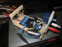
Finally got the Russian PIO input caps fitted along with upgraded Panasonic electrolytics for the power supply. Not the most elegant solution, but it sounds good 🙂.
I need to get round to putting it all in a proper case at some point. But I might wait until I've done all the mods/tweaks before I do that.
Next tweak is to add new inductors, tempted to be cheeky and get 4 samples of the 7447709100 WE-PD SMD power inductors from Wurth to try.
I need to get round to putting it all in a proper case at some point. But I might wait until I've done all the mods/tweaks before I do that.
Next tweak is to add new inductors, tempted to be cheeky and get 4 samples of the 7447709100 WE-PD SMD power inductors from Wurth to try.
Attachments
Last edited:
Wushuliu,
Wow, yours took even longer than mine which were 2 months. These boards are nice sounding and well built. Give it a try - I am curious how they compare to the YJ Blue board. They definitely deliver solid bass down to 20 Hz - an amazing feat for something so small. I also noted that connecting the mute pin to ground does not mute it. It runs very cool - no detectable temperature rise in either the inductors or the chip heatsink.
You can actually reproduce a listenable 20HZ? I cannot remember off hand any speaker manufacturer that advertised a response going down that low.
Finally got the Russian PIO input caps fitted along with upgraded Panasonic electrolytics for the power supply. Not the most elegant solution, but it sounds good 🙂.
I need to get round to putting it all in a proper case at some point. But I might wait until I've done all the mods/tweaks before I do that.
Next tweak is to add new inductors, tempted to be cheeky and get 4 samples of the 7447709100 WE-PD SMD power inductors from Wurth to try.
or 15uH for 8ohm speakers?
or 15uH for 8ohm speakers?
Ok, since I use 8 Ohm speakers I guess I'd better get some 15uH ones then 😀
Understanding output filters for Class-D amplifiers | EE Times
Is in general about outputfilters like in the TI datasheet, so not specifically only for ST. For these tpa chips I believe guru's🙂 said Fc=40.000/45.000 hz can be chosen. 45.000hz will be close with 15uH. With 10uH Fc will be higher? I guess, so switching noise surpressed less, maybe that leads to less efficiency so probably heat somewhere??
In another place it was advised if unshielded inductors were chosen to put them at other side of pcb, not component side (if possible) and glue them or strap them to pcb thightly so they cant move themselves. Don't know if the effects that lead to that advice are clearly audible, but it is why I only try the shielded inductors, like I said mechanically they look prettier LOL
You can actually reproduce a listenable 20HZ? I cannot remember off hand any speaker manufacturer that advertised a response going down that low.
Gradient Labs makes subwoofers that can extend this low. I am a big admirer of their speakers and design concepts. DIYers might benefit from taking a look and a listen. The set up I heard at the Dagogo show a couple years back was very impressive and at $11,000 compared to some of the $$$ it held it's own. My goal (challenge) is to get as real as close on my meager budget. Low low bass as well as high highs i.e. super tweeters give a lot to the illusion of live sounds in nature where we "sense" things in the vibratory frequency band that we can't necessarily ascribe a "tone" to.
Gradient Labs makes subwoofers that can extend this low. I am a big admirer of their speakers and design concepts. DIYers might benefit from taking a look and a listen. The set up I heard at the Dagogo show a couple years back was very impressive and at $11,000 compared to some of the $$$ it held it's own. My goal (challenge) is to get as real as close on my meager budget. Low low bass as well as high highs i.e. super tweeters give a lot to the illusion of live sounds in nature where we "sense" things in the vibratory frequency band that we can't necessarily ascribe a "tone" to.
You can actually reproduce a listenable 20HZ? I cannot remember off hand any speaker manufacturer that advertised a response going down that low.
Radioschmuck:
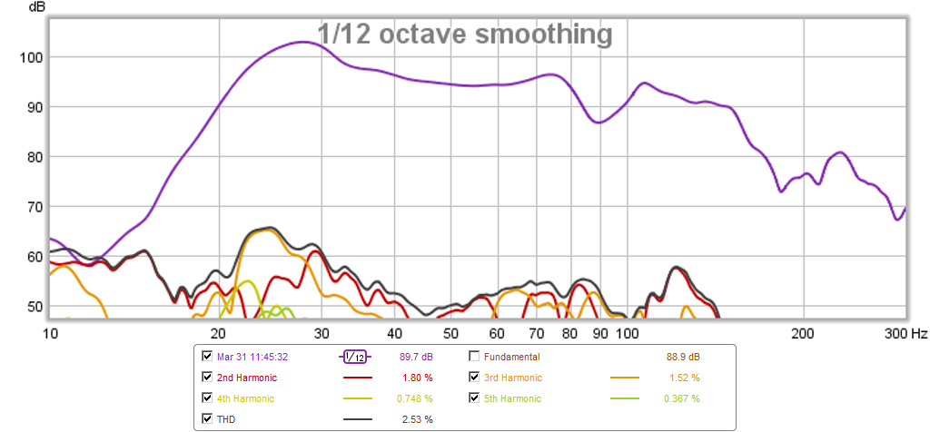
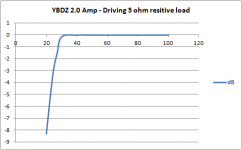
We don't all use commercially available speakers - did you forget that this is a DIY fourm? These are from sub woofers of my own design (a 4 foot long MLTL with 6.5 in driver), and yes, I can hear 20 Hz from them quite well. The YBDZ amp with stock 1 uF input cap will naturally have fall-of below the 40Hz. I believe TI recommends a 4 uF cap if you really want full amplitude at 20 Hz.
Here is a measurement of the RMS voltage drop on a 5 ohm resistive load in dB (6 volts nominal) from 100 Hz down to 20 Hz. It looks like there is a -8dB falloff in the amplitude voltage at 20 Hz - but you can still hear it from the sub.

And here is the output of the subwoofer's port:
Attachments

Understanding output filters for Class-D amplifiers | EE Times
Is in general about outputfilters like in the TI datasheet, so not specifically only for ST. For these tpa chips I believe guru's🙂 said Fc=40.000/45.000 hz can be chosen. 45.000hz will be close with 15uH. With 10uH Fc will be higher? I guess, so switching noise surpressed less, maybe that leads to less efficiency so probably heat somewhere??
In another place it was advised if unshielded inductors were chosen to put them at other side of pcb, not component side (if possible) and glue them or strap them to pcb thightly so they cant move themselves. Don't know if the effects that lead to that advice are clearly audible, but it is why I only try the shielded inductors, like I said mechanically they look prettier LOL
Thanks for the info/advice. I'm no expert so if someone has worked these things out or has experience of them I'll take their advice.
I prefer the look of the shielded inductors too, plus it sounds like the shielding has some benefits in terms of placement.
Have you tried turn on the amp with the volume pot at minimum (I assume you have a red YJ board)?
Regards,
Yeah and of course that works, but what I'm trying to accomplish is a boombox for a friend's small apartment and I think one of the main draws is that she can set the volume and only have to use an on/off switch without having to constantly search for that perfect volume. As well i have the bluetooth module wired to the same switch as the amp so upon power-on the bluetooth is not emitting a signal to the amp to prevent the speaker bump.
Oddly enough, a few weeks ago, I used some advice posted hundreds of pages ago and placed a 2.2uf 50v capacitor (non-polarized) from the mute pin to the Pvcc input from where I removed the barrel jack and it actually worked....then last night I was trying again without success.
So last night I tried placing a 10uf 50v cap from the SDZ pin to a ground point suggested around page 172 without success. I also tried placing the same cap from the MUTE pin to the suggested ground point with no success, and then I replicated my previous working solution without success again. As well I found the same capacitor I had previously used, the 2.2uf 50v non polarized one and attempted to replicate the working solution again with no success, only this time the barrel jack was still in place so I just soldered to the back exposed strip of metal while the Pvcc was soldered to the underside of the board. On my previous working solution the Pvcc was soldered to the top of the board and the capacitor was soldered to the Pvcc where it entered the board....
So how to delay with a capacitor and why might that work? Is this simply slowing the rush of electricity to the pin? That doesn't seem like what's happening to me...
So how to delay with a capacitor and why might that work? Is this simply slowing the rush of electricity to the pin? That doesn't seem like what's happening to me...
This is quite technical but also very precise description of a RC time constant circuit.
RC time constant - Wikipedia, the free encyclopedia
what kind of subwoofer is that?
It is a 4 ft long MLTL using a 6.5 woofer.
It is a 4 ft long MLTL using a 6.5 woofer.
pics or thread please!!
This is quite technical but also very precise description of a RC time constant circuit.
RC time constant - Wikipedia, the free encyclopedia
Thanks Saturnus. So if I am to understand correctly... the capacitor is slowing power to the MUTE pin which mutes the amplifier on startup until enough current is put to the MUTE pin? If this is the case, might removing power to the MUTE pin on the board and using the Pvcc and a capacitor to apply the power be the solution? Perhaps lifting one side of the 100k resistor off the board and attaching the capacitor from the Pvcc to the lifted side of the 100k resistor?
The only musical instrument that approaches 20HZ+/_ is a large pipe organ and there are probably not too many many music lovers that would appreciate that.Radioschmuck:
We don't all use commercially available speakers - did you forget that this is a DIY fourm? These are from sub woofers of my own design (a 4 foot long MLTL with 6.5 in driver), and yes, I can hear 20 Hz from them quite well. The YBDZ amp with stock 1 uF input cap will naturally have fall-of below the 40Hz. I believe TI recommends a 4 uF cap if you really want full amplitude at 20 Hz.
Here is a measurement of the RMS voltage drop on a 5 ohm resistive load in dB (6 volts nominal) from 100 Hz down to 20 Hz. It looks like there is a -8dB falloff in the amplitude voltage at 20 Hz - but you can still hear it from the sub.
http://www.diyaudio.com/forums/attachments/class-d/409310d1396283169-tpa3116d2-amp-ybdz-amp-5-ohm-load-
lf.png
And here is the output of the subwoofer's port:
pics or thread please!!
It's posted in the FC thread here: http://www.diyaudio.com/forums/full-range/223313-foam-core-board-speaker-enclosures-210.html#post3754821
I used two of them aimed into the corner of my room connected in series for an 8ohm load. They are not super loud SPL wise compared to a TH with a real sub driver but enough to hit the bass notes that every time I use them in the basement swmbo complains that they are too loud.
Sometimes we spend too much time futzing with our gear and forget to just listen to the music. I plugged my tpa3116 (Dug's PCB) straight into my full range mini Karlsonators and listened to some Van Morrison - no DSP no XO no BSC just pure lossless flac file. It sounds great. This is a really nice sounding amp and nothing better than playing fullrange.
Very true, I'm coming from the other direction though. I've been listening to my cardboard prototype OB's for months and months using a crossover from a random old speaker to cut off the bass from my full rangers (at some arbitrary frequency I don't even know) and just running the basses full range and using a simple digital EQ in my music player to level out the frequencies a bit by ear. It really shouldn't, but it sounds GREAT. Obviously nowhere near full potential though compared to when I actually get around to going full active and measuring things and using a custom crossover (DSP, going with the Najda I think, fed via I2S from my Raspberry PI). Thus I really need to get my **** together and one thing I need is more amplification.
I have a few questions though. My speakers use a 5" full range and two 10" woofers per side. I want the amps to be right at the speakers with short speaker leads and away from the source and DSP. The full ranger should do fine with a single channel of the TPA3116 but I will need some more power for my basses and was thinking of connecting them so they'll show a 2 ohm load and thus be able to suck some more power out of the TPA3116 (running parallell bridged). But no matter how I go about it I will have an unused channel per speaker.
This raises a few questions.
1. Will simply shorting this extra channel with a dummy load create any kinds of problems long term?
2. If not, how do I choose the load, go with 16ohms so there'll be little power or is there anything else I should think of (apart from using a decently rated resistor)?
I figure that the blue YJ as well as the green one which can easily be parallelled should be ok choices for amps. Has anyone compared them in stock form? I have read the WHOLE thread, but it's so much information to process I may have missed such a comparison. I will probably buy both in any case, but more information never hurts.
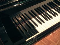
Not really. A simple 5-string bass will go to about 30Hz in standard tuning, and they are frequently tuned lower. Any standard piano will go below 30Hz and some models even go well below 20Hz. Then there's synth basses, which will go as low as you want. In short, there's plenty of music with real 20-30Hz musical content and even some that go lower. What's wrong with some earth shattering organ music now and then for that matter?The only musical instrument that approaches 20HZ+/_ is a large pipe organ and there are probably not too many many music lovers that would appreciate that.
Apart from all that, a lot of us enjoy movies with good sound as well, and sound effects in movies not seldom have as low as 10Hz content in them. To recreate 10Hz at theatre levels requires some serious hardware to be sure, but to imply that having a system that goes straight to 20Hz is somehow pointless is silly.
- Home
- Amplifiers
- Class D
- TPA3116D2 Amp