Hi all
I decided to do a total re-cap on my dear SX-1080, which I brought back to denmark i 1980, since the sound quality eventually was at poor transistorradio level.
So I ordered a bunch of caps, a couple of pots, transistors, diodes and resistors.
To cut it short I now have the problem, that there is no output 🙁
On the left channel I can easily adjust idle current to 30mV, but center voltage is (pin #10 at power amp) at +3.15 V.
On the right channel idle current can't be adjustet at all - it's "dead" at 0.0000V, as center voltage is at -1.18V.
I also replaced the 4.7 Ohm, 1 watt resistors at the main heatsink assy (all 8 of them), even though they all were reeading 5.05-5.30 Ohms, but that didn't do any difference.
I'd really appreciate any input that could come up with a hint where to look.
I have taken a lot of readings all over I can post, if needed, but I just want to open with this for starters.
/Ole
Hi Ole, can you show on schematic what exactly caps you have replaced?
Or just name them (I've got the service manual). This may help to come up with some ideas...
BR,
Valery
Or just name them (I've got the service manual). This may help to come up with some ideas...
BR,
Valery
Hi Ole, can you show on schematic what exactly caps you have replaced?
Or just name them (I've got the service manual). This may help to come up with some ideas...
BR,
Valery
Hi Valery
Sorry 'bout the late reply - had to take junoir to a Basketball game.
Yes, I got the whole list and I have uploaded it.
I have also uploaded my observations after the initial power on after re-capping - perhaps that can be of use as well?
Attachments
Ole, you also changed some transistors with substitutes - are you sure B-C-E are at the right places?
If yes, let's do some troubleshooting.
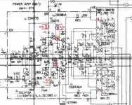
1) First of all, I would disconnect the output stage collectors from the rails, just to be on a safe side (it's easy to kill them, also if some of them are already dead, they will not affect the rest of the circuit). So disconnect the wires from pins 14 and 21 in both channels. Without the output load the drivers' (Q6, Q7) current will be enough to balance the amp.
2) Power-on, check the rails - pins 8, 1, 12, 22 (+/-60v, +/-62v respectively).
3) Check what you've for at the output and at Q6, Q7 bases.
4) Check the voltages at R11, R9 and R12 (1.2v, 0.9v, 0.9v).
Tell me what you see )
P.S. Be careful when measuring - easy to shorten something... 120v between the rails is rather serious stuff )
If yes, let's do some troubleshooting.
1) First of all, I would disconnect the output stage collectors from the rails, just to be on a safe side (it's easy to kill them, also if some of them are already dead, they will not affect the rest of the circuit). So disconnect the wires from pins 14 and 21 in both channels. Without the output load the drivers' (Q6, Q7) current will be enough to balance the amp.
2) Power-on, check the rails - pins 8, 1, 12, 22 (+/-60v, +/-62v respectively).
3) Check what you've for at the output and at Q6, Q7 bases.
4) Check the voltages at R11, R9 and R12 (1.2v, 0.9v, 0.9v).
Tell me what you see )
P.S. Be careful when measuring - easy to shorten something... 120v between the rails is rather serious stuff )
Attachments
Hi Valery
I trust you got my PM...
Well here are som numbers:
So, Left R11 is off, as is all three Right R9, R11 & R12.
Also pin 1 on both Channels are way off.
I must confess that I do not know what exactly you are asking in "3) Check what you've for at the output and at Q6, Q7 bases."
Connecting one lead to base I get, but I don't know where to connect the other lead ? To GND ?
emitter?
collector?
Sorry for being such a noob.
Also I must confess I'm not exactly sure if all transistors are placed correctly b-c-e wise.
I have been leaning on "hopjohn"s project on Audiokarma.org, and comparing this photo
SX-1080 What to know before diving in? - Page 2 - AudioKarma.org Home Audio Stereo Discussion Forums
to mine:
https://drive.google.com/file/d/0B-K7vfu8iewrTVRRMnhGLVBXWUE/edit?usp=sharing.
Again I know this close to a guessing game, and I suspect myself this can be where the problem lies. I did try to find an explantion, but without success, sorry ;-)
I trust you got my PM...
Ole, you also changed some transistors with substitutes - are you sure B-C-E are at the right places?
If yes, let's do some troubleshooting.
1) First of all, I would disconnect the output stage collectors from the rails, just to be on a safe side (it's easy to kill them, also if some of them are already dead, they will not affect the rest of the circuit). So disconnect the wires from pins 14 and 21 in both channels. Without the output load the drivers' (Q6, Q7) current will be enough to balance the amp.
2) Power-on, check the rails - pins 8, 1, 12, 22 (+/-60v, +/-62v respectively).
3) Check what you've for at the output and at Q6, Q7 bases.
4) Check the voltages at R11, R9 and R12 (1.2v, 0.9v, 0.9v).
Tell me what you see )
P.S. Be careful when measuring - easy to shorten something... 120v between the rails is rather serious stuff )
Well here are som numbers:
HTML:
Power amp assy, Left CH
+	-	V(actual)	V(Specs)
1	chass	-0,15		-60,00
8	chass	+64,60		+60,00
12	chass	+62,50		+62,00
22	chass	-62,50		-62,00
------------------------------------------
R9		+0,90		+0,90
R11		+0,76		+1,20
R12		+0,93		+0,90

Power amp assy, Right CH
+	-	V(actual)	V(Specs)
1	chass	-2,00		-60,00
8	chass	+64,00		+60,00
12	chass	+62,50		+62,00
22	chass	-62,00		-62,00
------------------------------------------
R9		+0,00		+0,90
R11		+0,00		+1,20
R12		+0,00		+0,90
So, Left R11 is off, as is all three Right R9, R11 & R12.
Also pin 1 on both Channels are way off.
I must confess that I do not know what exactly you are asking in "3) Check what you've for at the output and at Q6, Q7 bases."
Connecting one lead to base I get, but I don't know where to connect the other lead ? To GND ?
emitter?
collector?
Sorry for being such a noob.
Also I must confess I'm not exactly sure if all transistors are placed correctly b-c-e wise.
I have been leaning on "hopjohn"s project on Audiokarma.org, and comparing this photo
SX-1080 What to know before diving in? - Page 2 - AudioKarma.org Home Audio Stereo Discussion Forums
An externally hosted image should be here but it was not working when we last tested it.
to mine:
https://drive.google.com/file/d/0B-K7vfu8iewrTVRRMnhGLVBXWUE/edit?usp=sharing.
Again I know this close to a guessing game, and I suspect myself this can be where the problem lies. I did try to find an explantion, but without success, sorry ;-)
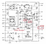
Hi Ole, we've got a very good result right away. We're missing -60V regulated rail.
So now we move to the Power Supply Assembly and see what we can find there.
Start with checking -76V, then chek the other couple of points marked by red boxes. Also see if there are some burnt resistors, etc.
If -76V is in place, then the problem is in one of the transistors, most likely Q4.
Before we get -60V back, it does not make sense to do anything with the power amp - it will not work anyway.
Let's see what we've got 😉
Valery
P.S. In 3) i meant measuring against the ground, you are right.
Attachments
Last edited:
Hi Ole, we've got a very good result right away. We're missing -60V regulated rail.
So now we move to the Power Supply Assembly and see what we can find there.
Start with checking -76V, then chek the other couple of points marked by red boxes. Also see if there are some burnt resistors, etc.
If -76V is in place, then the problem is in one of the transistors, most likely Q4.
Before we get -60V back, it does not make sense to do anything with the power amp - it will not work anyway.
Let's see what we've got 😉
Valery
Coming right up

Was there supposed to be a picture with your answer where you refer to "the point marked by red boxes"?Hi Ole, we've got a very good result right away. We're missing -60V regulated rail.
So now we move to the Power Supply Assembly and see what we can find there.
Start with checking -76V, then chek the other couple of points marked by red boxes. Also see if there are some burnt resistors, etc.
If -76V is in place, then the problem is in one of the transistors, most likely Q4.
Before we get -60V back, it does not make sense to do anything with the power amp - it will not work anyway.
Let's see what we've got 😉
Valery
P.S. In 3) i meant measuring against the ground, you are right.
Sorry - forgot to attach the picture - now it's there 🙂
Phew - this is hard - I need to find and end-connect to R8...
OK, I read:
-86V between R8 (end away from edge) and GND.
-0.11 on pin 27
Am I doing this correct:
Black lead to GND
Red lead to pinmarked "13V" on Q3?: Reading is 0.00008V
Red lead to pinmarked "13.6V" on Q3?: Reading is 0.00007V
Last edited:
Well, if R8 itself is OK (not broken to infinite R), most likely the problem is Q4.
pls try to measure R8 (with power off) and if it is somewhat close to 2.2R, can you solder Q4 out?
BTW, if C16 or C18 is bad or soldered-in with wrong polarity - it will also lead to similar effect...
pls try to measure R8 (with power off) and if it is somewhat close to 2.2R, can you solder Q4 out?
BTW, if C16 or C18 is bad or soldered-in with wrong polarity - it will also lead to similar effect...
Last edited:
Well, if R8 itself is OK (not broken to infinite R), most likely the problem is Q4.
pls try to measure R8 (with power off) and if it is somewhat close to 2.2R, can you solder Q4 out?
BTW, if C16 or C18 is bad or soldered-in with wrong polarity - it will also lead to similar effect...
I will lift a lead off R8 and check, and re-check C16 and C18
Well - whadda you know. R8 is dead!
I'll check if I have one in the pile...
I have a 2.3 that reads 2.5 Ohms - I guess I can use it?
Last edited:
Ah, cool. We're coming closer )
After you change R8 to the new one, before powering on, make sure the output stage collectors are disconnected from the power amp board. It will be much safer to start it this way.
After you change R8 to the new one, before powering on, make sure the output stage collectors are disconnected from the power amp board. It will be much safer to start it this way.
yes, you are doing right!
is there the same -86V at the other end of R8?
Thanks!
I can't get a reading from the other end of R8.
And here I need to supply some further info:
About a year ago I had to do a repair. The middle lead on Q4 had - over time - pulled down strongly enough to rip the lead-track off of the print-board, such that the middle lead of Q4 was out of circuit. The repair I did was to solder a piece of wire from middle lead of Q4 to the connecting point of the end of the lead-track, which is where R8 is mounted at end near D9. The repair had been working and i do not suspect this is part of the problem.
I will now replace R8.
Well...
R8 replaced, power on
Voltage on R8-away-edge, starts on -76, increases to ca. -82-83-84,
then Q3 blow its top off (literally)!
R8 replaced, power on
Voltage on R8-away-edge, starts on -76, increases to ca. -82-83-84,
then Q3 blow its top off (literally)!
Oops...
The reason may be C20 - if it suffers current leak, collector current of Q3 would raise to infinity. Also, Q4 needs to be checked ( better solder it out for measurement).
The reason may be C20 - if it suffers current leak, collector current of Q3 would raise to infinity. Also, Q4 needs to be checked ( better solder it out for measurement).
OK.
Checking C20 and Q4 - will solder out.
Please advice how to check Q4 in detail - transistors are not trivial to me....
Checking C20 and Q4 - will solder out.
Please advice how to check Q4 in detail - transistors are not trivial to me....
- Status
- Not open for further replies.
- Home
- Amplifiers
- Solid State
- Pioneer SX-1080, after re-cap problem w. center voltage & idle current