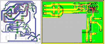
Try to reduce the area of the red and orange loops (those are the load currents on negative and positive swing respectively). Note how my un-optimized layout has relatively small loops. There's plenty of room for optimization in my layout. I'm still working on that...
~Tom
~Tom
Attachments
Last edited:
Try to reduce the area of the red and orange loops (those are the load currents on negative and positive swing respectively). Note how my un-optimized layout has relatively small loops. There's plenty of room for optimization in my layout. I'm still working on that...
~Tom
OK, here is another try based on the above advice to the best of my understanding.

That's better on the output, however, I suggest moving your ground 'blob' up to the smaller decoupling caps and making that the star ground. Maybe that means the Zobel cap rotates 90 degrees and the Zobel resistor scoots over. Personally, I'd rotate Czobel 180 degrees and put it side by side with Rzobel.
How are you planning to connect the op-amp ground to the LM3886 ground?
~Tom
How are you planning to connect the op-amp ground to the LM3886 ground?
~Tom
That's better on the output, however, I suggest moving your ground 'blob' up to the smaller decoupling caps and making that the star ground. Maybe that means the Zobel cap rotates 90 degrees and the Zobel resistor scoots over. Personally, I'd rotate Czobel 180 degrees and put it side by side with Rzobel.
How are you planning to connect the op-amp ground to the LM3886 ground?
~Tom
Hi Tom,
I was gonna post another update so i'll take these points in the next time. In this new layout the star ground is there for the high current part of the circuit (the LM3886 part) and i added a ground plane for the low current part (the LME49710 part) hopefully to get the best of both worlds. Was that a bad idea?
An externally hosted image should be here but it was not working when we last tested it.
That's better on the output, however, I suggest moving your ground 'blob' up to the smaller decoupling caps and making that the star ground. Maybe that means the Zobel cap rotates 90 degrees and the Zobel resistor scoots over. Personally, I'd rotate Czobel 180 degrees and put it side by side with Rzobel.
Made some changes as per your post...
An externally hosted image should be here but it was not working when we last tested it.
How are you planning to connect the op-amp ground to the LM3886 ground?
Jumper wire on bottom side of the board between the two red circled points.
Here is the layout after some minor changes...

also if i wanted to add a volume pot (50K linear), What changes needed in the input filter shown below?

Last edited:
Mmmmm.... A 50 k pot. So worst case output impedance 25 kOhm. That's probably OK. In that case, no changes are needed. You could eliminate R6 if you wanted to as the pot will discharge C9 to ground. As long as the wiper is connected anyway.
I'd scoot the opamp closer to the LM3886, though. You don't need the fat trace on the input. It doesn't hurt, but it's not needed. But trace the output from the opamp into the LM3886 and its return path through the star ground. That's a pretty long loop. See if you can do anything to reduce it.
~Tom
Last edited:
Mmmmm.... A 50 k pot. So worst case output impedance 25 kOhm. That's probably OK. In that case, no changes are needed. You could eliminate R6 if you wanted to as the pot will discharge C9 to ground. As long as the wiper is connected anyway.
A 50K linear pot, so in order to get a semi log response it need a parallel resistance in the range of 2.5k to 5k. Is that still okay?
I'd scoot the opamp closer to the LM3886, though. You don't need the fat trace on the input. It doesn't hurt, but it's not needed. But trace the output from the opamp into the LM3886 and its return path through the star ground. That's a pretty long loop. See if you can do anything to reduce it.
A few question about the board so far...
1- Is it okay to connect the two star grounds through a jumper wire?
2- Is the ground plane for the op amp (low current) suitable or it needs a star ground?
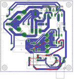
Moved the op amp closer to the LM3886, now the input and output traces of the op amp is shorter but i guess the supply loop is still long?

A few question about the board so far...
1- Is it okay to connect the two star grounds through a jumper wire?
2- Is the ground plane for the op amp (low current) suitable or it needs a star ground?
A few question about the board so far...
1- Is it okay to connect the two star grounds through a jumper wire?
2- Is the ground plane for the op amp (low current) suitable or it needs a star ground?
Power pin4 seems to not have a supply connection.
The HF decoupling still have long routes.
The input loop area is still big.
The HF decoupling still have long routes.
The input loop area is still big.
A 50K linear pot, so in order to get a semi log response it need a parallel resistance in the range of 2.5k to 5k. Is that still okay?
Before going down that route, I suggest reading the chapter on volume controls in Douglas Self, "Small Signal Audio Design". I found it rather eye-opening. You can also set up a simulation in your favorite circuit simulator. Sweep the wiper position on the pot and plot the attenuation versus wiper position. You want a true logarithmic function - i.e. a straight line when you plot attenuation in dB versus rotation of the pot shaft in degrees.
An audio taper ("logarithmic") pot will give you a piecewise linear curve. I.e. two different logarithmic tapers. So basically, you have fine control over the high attenuations but coarse control over the low attenuations.
The "log cheater" approach where you load a linear pot with a resistor to approach a log pot gives you the opposite. Coarse control from infinite to about 25 dB attenuation then fine control from there to 0 dB attenuation. I suspect this is not what you want. Basically, the amp will go from "can't hear anything" to "loud" if you breathe on the volume knob.
1- Is it okay to connect the two star grounds through a jumper wire?
Sure. Just make sure no current flows in the wire - at least no current not related to the opamp.
2- Is the ground plane for the op amp (low current) suitable or it needs a star ground?
I think a plane is fine. You can probably expand it around the input circuitry.
Moved the op amp closer to the LM3886, now the input and output traces of the op amp is shorter but i guess the supply loop is still long?
You can minimize the area of the loop by routing VCC, GND close and VEE, GND close.
Power pin4 seems to not have a supply connection.
Good catch! Yeah... The op-amp needs power to VEE.
Are you routing this without a netlist? I haven't done that in years (or decades)... My flow is schematic -> netlist -> layout. That way, if the schematic is drawn correctly, the layout will at least be hooked up correctly (assuming there are no unconnected routes). At the end of the layout process, I have the tool auto-generate reports of unrolled nets and DRC errors. If no errors, fab it!
The input loop area is still big.
Tru dat. That would be my next step.
~Tom
What could be moved and where to minimize the input loop area?
An externally hosted image should be here but it was not working when we last tested it.
I've drawn the loop for you. Try to minimize it.
Now that you've made the board wider, you could also move Cmute to the other side of the LM3886. This would allow you to reduce the Y dimension and bring the LM3886 closer to the edge of the board. It'll be easier to attach to a heat sink that way.
~Tom
Now that you've made the board wider, you could also move Cmute to the other side of the LM3886. This would allow you to reduce the Y dimension and bring the LM3886 closer to the edge of the board. It'll be easier to attach to a heat sink that way.
~Tom
Attachments
Last edited:
The non-inverting input of the LM3886 should connect to the op-amp ground by its decoupling caps.
You probably also want to space the two series resistors for the zeners further apart and away from the electrolytic can. 'Lytics don't care much for heat...
~Tom
You probably also want to space the two series resistors for the zeners further apart and away from the electrolytic can. 'Lytics don't care much for heat...
~Tom
I've drawn the loop for you. Try to minimize it.
I can see the loop but i can't think of a way to minimize it with the current component size (1uF and 4.7 Ohm), shortened traces a bit though.
The non-inverting input of the LM3886 should connect to the op-amp ground by its decoupling caps.
Not to the audio (input) ground?
An externally hosted image should be here but it was not working when we last tested it.
I can see the loop but i can't think of a way to minimize it with the current component size (1uF and 4.7 Ohm), shortened traces a bit though.
There's no reason to use a power resistor for the 4.7 ohm. There should be no current flowing there. I'm not sure about your reasoning there...
Would you be able to tighten up the loop area if you rotated the input cap 90 degrees and put it to the right of the input connector north of the mounting hole?
Not to the audio (input) ground?
I think of the inputs to the LM3886 as a pseudo-differential pair. They should be coupled pretty tightly and terminate as close to the driving circuit as possible. The ground reference should be that of the opamp. That's the exact same thinking as we went through on the output of the LM3886.
~Tom
There's no reason to use a power resistor for the 4.7 ohm. There should be no current flowing there. I'm not sure about your reasoning there...
Would you be able to tighten up the loop area if you rotated the input cap 90 degrees and put it to the right of the input connector north of the mounting hole?
Changed the resistor 4.7 Ohm to a smaller one and moved it closer to the audio ground. The cap must on this side of the input connector (left side) because of the input pin location.
I think of the inputs to the LM3886 as a pseudo-differential pair. They should be coupled pretty tightly and terminate as close to the driving circuit as possible. The ground reference should be that of the opamp. That's the exact same thinking as we went through on the output of the LM3886.
You want to connect the amplifier positive terminal to the power ground?
An externally hosted image should be here but it was not working when we last tested it.
Last edited:
The non-inverting input of the LM3886 (pin 10) is the input ground reference for your amp. It should connect to the ground reference of the driving op-amp as this minimizes the loop area of the op-amp -> LM3886 circuit as far as I can tell.
The route through the input cap is still mighty long. I wonder if you can make the route shorter by rotating the cap 90 degrees and placing along the right edge of the board.
~Tom
The route through the input cap is still mighty long. I wonder if you can make the route shorter by rotating the cap 90 degrees and placing along the right edge of the board.
~Tom
The non-inverting input of the LM3886 (pin 10) is the input ground reference for your amp. It should connect to the ground reference of the driving op-amp as this minimizes the loop area of the op-amp -> LM3886 circuit as far as I can tell.
In Cordell's book the power amplifier positive terminal is connected to the "quiet ground" i.e. the signal ground which is connected to the power ground only through the 4.7 Ohm resistor.
The route through the input cap is still mighty long. I wonder if you can make the route shorter by rotating the cap 90 degrees and placing along the right edge of the board.
I'll try that and post again soon.
In Cordell's book the power amplifier positive terminal is connected to the "quiet ground" i.e. the signal ground which is connected to the power ground only through the 4.7 Ohm resistor.
Yep. And to replicate this in your circuit, connect the 4.7 Ω from the ground star by the LM3886 to the ground plane by the op-amp. Then connect the input ground and LM3886 non-inverting input to the ground plane by the opamp.
~Tom
- Status
- Not open for further replies.
- Home
- Amplifiers
- Chip Amps
- Inverting LM3886