
There is no point including the centre tap or ground lead in the twist. It's normal to twist the AC leads to the rectifier bridge together and the DC rail leads to and from the smoothing caps. where they are not all simply mounted on the PCB.
The idea is to twist the feed and return leads of all high current circuits. Whether AC or DC power, these leads will have anti-phase ripple currents which means their stray fields may cancel when the leads from ends of the winding are tightly wrapped or brought close together. There doesn't seem, according to D. Self at least, to be any advantage in including the ground or centre tap leads in the twist.
You have 3 transformer secondaries, forget the lamp winding which is single with one side grounded.
The others have grounded centre-taps and their lead pairs, Red and Yellow, to the amplifier and low voltage supply rectifiers, can be twisted. It would take a PCB diagram to specify what could or should be done with power supply wiring from the rectifier to the amplifier and preamp. but you will understand now what is necessary, if there is indeed any wiring from the supply onward.
Other candidates for twisting - Long runs and returns of mains leads, such as to the power switch. and from power selector to transformer. The speaker leads to the output terminals. Don't mess with the voltage switch wiring - it will be hopeless trying to twist anything there.
Hi Ian,
Thanks for your help.
Its a multi pcb amp connected with copious amounts of wire, from the rectifier its wired onto the resivoir capacitors (would I twist those as well?) and then from there dished out to the different supply's, with the v+ and v- going to the power amps is it a good idea to twist those?
Thanks for your help.
It would take a PCB diagram to specify what could or should be done with power supply wiring from the rectifier to the amplifier and preamp. but you will understand now what is necessary, if there is indeed any wiring from the supply onward.
Its a multi pcb amp connected with copious amounts of wire, from the rectifier its wired onto the resivoir capacitors (would I twist those as well?) and then from there dished out to the different supply's, with the v+ and v- going to the power amps is it a good idea to twist those?
disagree - but physical details make all the difference
xfmr sec center taps often should be routed alongside/twisted with the pair past fuses, rectifiers and then connected to the reservoir caps junction
because there can be current in the CT due to cap imbalance in value/impedance and in any grounded load's phase giving unbalanced charge/discharge
usually the better system gnd point is the junction of the reservoir cap's leads - not the xfmr CT
with multiple channels you may have to compromise with hierarchical "clean and dirty" gnd - pure star gnd may be too simplistic
Last edited:
Yes that's what I meant by "understand what's necessary". As I pointed out, you twist the feed and return leads of power supplies. In this case, +and- rails, neglecting the CT, 0V, midpoint or whatever you want to call it.
As you seem unsure of this, might I suggest you get hold of Self, Cordell or Slone's amplifier books and do a bit of reading on the wiring. Absolutely wonderful stuff in their books if you are interested and need to understand and do this kind of work more than once. The amount of time and concern over these things gets reduced considerably and makes it a doddle when you know what you are trying to do. I would say that a lot of refinements like wire arrangements can be lost in old amplifiers because of the fundamental noise and distortion problems so unless the amplifier is already very quiet and clear sounding, you may not hear much if any improvement.
If cash is a concern, you can download Self's 4th Edition of "Audio Power Amplifier Design Handbook" free. There are other sources but this one works reliably and seems legit. Store the URL as you may have to download each time you want to read, if you can't save the PDF to file. https://bgaudioclub.org/uploads/docs/Audio_Power_Amplifier_Design_Handbook_4th_Edition.pdf
All the wires that have a Flow and Return benefit from a twisted topology to minimise EMI.
A centre-tapped secondary has some current passing along the centre-tap wire. (if the centre tap wire NEVER passed any current then it would NEVER be needed.)
When this centre-tap current is flowing the current in the other two wires is NOT the SAME.
If one requires cancellation of the fields of the Flow and Return wires then the centre-tapped secondary MUST be run as a twisted triplet to the rectifier.
The output from the rectifier MUST be run as a twisted triplet to the series connected smoothing capacitors.
The output from the smoothing capacitors MUST be run as a twisted triplet to the next stage.
Last edited:
There is no point including the centre tap or ground lead in the twist. It's normal to twist the AC leads to the rectifier bridge together and the DC rail leads to and from the smoothing caps. where they are not all simply mounted on the PCB.
The idea is to twist the feed and return leads of all high current circuits. Whether AC or DC power, these leads will have anti-phase ripple currents which means their stray fields may cancel when the leads from ends of the winding are tightly wrapped or brought close together. There doesn't seem, according to D. Self at least, to be any advantage in including the ground or centre tap leads in the twist.
I think that might be correct only if the supply caps are identically discharged, like a sine wave at 5 or 10 KHz. But I suspect that low frequencies will deplete one cap more than the other, in which case the center tap wire will be running current.
Twisting all three guarantees net zero current in the bundle.
jn
edit: or, more eloquently......"what they said"..😱
Last edited:
busy plot but shows CT current(red trace) plainly for gnded load
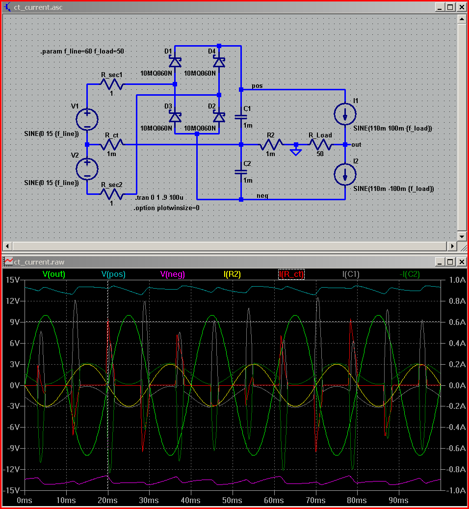
also shows load return current in R2 (yellow) - which is only linear as shown for Class A output stage operation
also shows load return current in R2 (yellow) - which is only linear as shown for Class A output stage operation
Last edited:
You know, I believed that 3 wire bundles were the best and built amplifiers with 3 wire twists for many years. Then I read Self's work and saw a comparison run on an AP2 of a pair of my amplifiers and realised it didn't make any practical difference whether ground was included or not to the degree of cancellation. i.e. the distortion.
Note: I'm referring to Self in different degrees because each edition of his book spends more or less time on this topic. I think the 3rd edition of APADH has the longest description of the matter but I can't find it ATM.
I well understand the logical and simulated. proofs folks, but the client couldn't measure it. Neither could D.Self, if I understood correctly. He says in the 5th ed: "Keep the + & - HT supply wires to the amplifiers close together....Sometimes it seems more effective to include the 0V line in this cable run; if so it should be tightly braided to keep the wires in close proximity"
How's that for having a bet each way? Anyway, drawing from my own experience but not an AP any more, just the scope and Bench DVM, I'm in agreement with Mr Self and yet to find that the earth included was a better arrangement but that doesn't say that others won't get better results with either or that others are wrong in any respect.
PS xfmr CT is a different analysis
on the xfmr side the CT current in the C input rectified supply, separately ran, forms a loop which will radiate, possibly couple - no question
and this is a nasty,spikey nonlinear "beat frequency" between the audio signal frequency and the mains/ps rectifier recharge "pulse" frequency
I was too quick with the last line:
in fact load return current is always mostly linear - as linear as the load
it is the +/- PS wires to the output devices that have "haver-sine" currents in Class B operation
twisting just the +/- pair after the reservoir caps is adequate to suppress large nonlinear mag field radiation by virtue of the sum of the +/- supply wire's currents also being mostly linear - like the load gnd return
so your advice needs modifying: for runs between xfmr and rectifier/caps - CT current will give nonlinear magnetic field if not routed with the the winding pair
for PS caps to output devices the load return wire loop (to the Cap's gnd lead junction) with the twisted +/- wires would give mostly linear coupling - making for small linear gain/phase and possibly linear channel crosstalk - but not measured distortion with a linear load
you can then consider how relevant nonlinear load current to/from the speakers due to their often multiple % nonlinearities
then including the load return gnd with the ps wire bundle to better cancel all current loops/magnetic radiation/coupling in the amplifier seems like a better idea for the amplifier's performance #, even though almost certainly inaudible as a system effect in the presence of the speaker distortion associated with the speaker load nonlinearity
on the xfmr side the CT current in the C input rectified supply, separately ran, forms a loop which will radiate, possibly couple - no question
and this is a nasty,spikey nonlinear "beat frequency" between the audio signal frequency and the mains/ps rectifier recharge "pulse" frequency
I was too quick with the last line:
also shows load return current in R2 (yellow) - which is only linear as shown for Class A output stage operation
in fact load return current is always mostly linear - as linear as the load
it is the +/- PS wires to the output devices that have "haver-sine" currents in Class B operation
twisting just the +/- pair after the reservoir caps is adequate to suppress large nonlinear mag field radiation by virtue of the sum of the +/- supply wire's currents also being mostly linear - like the load gnd return
so your advice needs modifying: for runs between xfmr and rectifier/caps - CT current will give nonlinear magnetic field if not routed with the the winding pair
for PS caps to output devices the load return wire loop (to the Cap's gnd lead junction) with the twisted +/- wires would give mostly linear coupling - making for small linear gain/phase and possibly linear channel crosstalk - but not measured distortion with a linear load
you can then consider how relevant nonlinear load current to/from the speakers due to their often multiple % nonlinearities
then including the load return gnd with the ps wire bundle to better cancel all current loops/magnetic radiation/coupling in the amplifier seems like a better idea for the amplifier's performance #, even though almost certainly inaudible as a system effect in the presence of the speaker distortion associated with the speaker load nonlinearity
Last edited:
You know, I believed that 3 wire bundles were the best and built amplifiers with 3 wire twists for many years. Then I read Self's work and saw a comparison run on an AP2 of a pair of my amplifiers and realised it didn't make any practical difference whether ground was included or not to the degree of cancellation. i.e. the distortion.
Note: I'm referring to Self in different degrees because each edition of his book spends more or less time on this topic. I think the 3rd edition of APADH has the longest description of the matter but I can't find it ATM.
I well understand the logical and simulated. proofs folks, but the client couldn't measure it. Neither could D.Self, if I understood correctly. He says in the 5th ed: "Keep the + & - HT supply wires to the amplifiers close together....Sometimes it seems more effective to include the 0V line in this cable run; if so it should be tightly braided to keep the wires in close proximity"
How's that for having a bet each way? Anyway, drawing from my own experience but not an AP any more, just the scope and Bench DVM, I'm in agreement with Mr Self and yet to find that the earth included was a better arrangement but that doesn't say that others won't get better results with either or that others are wrong in any respect.
The test results will depend heavily on the physical design of the hardware. If plus and minus are twisted but independent of the CT, then you will indeed generate the pulse currents and magfield as jcx has presented.
My biggest concern would be proximity of these currents to the chassis, and more precisely, the chassis metal between the input connector ground and the chassis safety bond. Coupling to the chassis in this fashion may NOT show up on the test bench, as there is typically no ground loop formed with very good test equipment. However, once a source is connected via IC's, that coupling to chassis may cause ground loop currents through the IC braid, and it will be that very ugly haversine style signal. edit: ground loop chassis currents from the input connector should not run close to any ground reference wiring, be it the input connector, the feedback divider ground, pcboard grounds and traces...
My belief is that ALL currents within a chassis must be field zero'd by twisting, coax, or stripline methods. This is not very easy if one splits the output pass elements into two heatsinks.
edit: found my pic, located in this post.
Here's a demo of what I meant. The white is CT, the blue wires are AC feed, the red is pos, black is neg. Note: I do not recommend simply tacking wires like that, but I had a GBU8K on my desk, so used it. Also, it's not necessary to keep this linear geometry, that was just for my convienience. White is #12, others are #14, so braiding or even bending wasn't possible while keeping the bridge leads straight..
Note the AC (ground) simply passes through the neighborhood. It goes directly to supply cap center. The ties keep the wire spacing minimal.
Note also that the triad grouping minimizes rail to rail inductance as well.
jn
jn
Last edited:
I had a strong notion that would be content of your next post, jcx; re: transformer V amplifier side of the rectifiers. I don't know the actual physical wiring arrangement because we don't even know the relevant construction details. Perhaps reddish will respond with the present physical wiring details of the CT grounding which I suspect, is at the transformer first, along with preamp and lighting grounds at least.
I avoid unravelling a jumble like that if it is the case but I concede that all transformer grounds should ideally be lifted and made up in flex similar to the AC leads and the ground connection remade after twisting with them, at the end of a "T" to the common connection of the smoothing caps.
The rest is as I suggested as I don't think great benefits are to be had there.
BTW. Many thanks for your time and effort, jcx. It doesn't go unnoticed.
sorry, jnuetron didn't see your post - this thread is ticking over.
Perhaps reddish will respond with the present physical wiring details of the CT grounding which I suspect, is at the transformer first, along with preamp and lighting grounds at least.
CT is grounded near the transformer (it would be difficult to include this in the 'twist' as the wire is a lot shorter), grounded with as suspected the lighting grounds, the common pins on the reservoir caps and pins 16 and 20 of board ref 719-0004-00.
the Connection of the Main Audio Ground to Chassis has NOTHING to do with Audio Quality.
This connection is for SAFETY only.
It's job is to pass Fault Current to PE. The connection has to be made to allow upto kA to pass to Chassis and can be from any part of the wiring that is capable of passing that Fault Current.
This connection is for SAFETY only.
It's job is to pass Fault Current to PE. The connection has to be made to allow upto kA to pass to Chassis and can be from any part of the wiring that is capable of passing that Fault Current.
Getting the CT grounding right is probably more important that twisting. Almost everyone instinctively gets this wrong, by grounding the CT near the transformer. The CT should never be directly grounded. It should always be connected to the reservoir cap CT, then that in turn should be grounded at the quiet, clean end of the PSU.
DF,
your post15 does not differentiate between the Audio Grounding of the PSU, otherwise known as PSU Zero Volts
and
the Safety Earthing of the PSU Zero Volts.
These are two quite different items that are handled differently.
Your post
Post14
I think some of the earlier posters have mixed up the two different connections by using the word "ground" to cover everything.
eg.
your post15 does not differentiate between the Audio Grounding of the PSU, otherwise known as PSU Zero Volts
and
the Safety Earthing of the PSU Zero Volts.
These are two quite different items that are handled differently.
Your post
is referring to the Audio Grounding for the PSU Zero Volts to supply clean power to the Audio Circuits.the reservoir cap CT, then that in turn should be grounded at the quiet, clean end of the PSU
Post14
is referring to the Safety Earth and allows Fault Current to pass via the Chassis to PE.Main Audio Ground to Chassis.............
This connection is for SAFETY only.
It's job is to pass Fault Current to PE. The connection has to be made to allow upto kA to pass to Chassis
I think some of the earlier posters have mixed up the two different connections by using the word "ground" to cover everything.
eg.
gives the impression (at least to me) that all the transformer connections are isolated (lifted?) from the Chassis and that none are connected via the Chassis to PE.all transformer grounds should ideally be lifted and made up in flex similar to the AC leads and the ground connection remade after twisting with them,......to the common connection of the smoothing caps.
Last edited:
I did not differentiate because I was speaking of only one ground - the signal ground. The CT grounding has nothing whatsoever to do with safety ground.
I was commenting on post 13, not post 14.
I was commenting on post 13, not post 14.
The CT "ground" is connected to the PSU Zero Volts and also connected to the Main Audio Ground.
It is this extensive ground that needs to be protected by a connection to Chassis and thus pass Fault Current to PE.
There are TWO CONNECTIONS
one is audio related the other is Safety related.
Your post skims past the Safety related connection by omitting it.
The comment in post13 uses the general word "ground"
He could simply be referring to connecting the CT (centre tap) to the PSU Zero Volts at the junction between the smoothing caps. Yes it too can and should be near the transformer.
Or
He could be referring to connecting the CT to Chassis.
I can't tell. The post is ambiguous because of the misuse of the word "ground".
It is this extensive ground that needs to be protected by a connection to Chassis and thus pass Fault Current to PE.
There are TWO CONNECTIONS
one is audio related the other is Safety related.
Your post skims past the Safety related connection by omitting it.
The comment in post13 uses the general word "ground"
and this is typical for ambiguity and the Safety Problems that can ensue.CT is grounded near the transformer
He could simply be referring to connecting the CT (centre tap) to the PSU Zero Volts at the junction between the smoothing caps. Yes it too can and should be near the transformer.
Or
He could be referring to connecting the CT to Chassis.
I can't tell. The post is ambiguous because of the misuse of the word "ground".
Last edited:
I didn't "skim past" anything. When I speak of something, there is an infinity of things I am not speaking of. I therefore do not list all the things I am not speaking of.
Grounding the transformer CT has nothing whatsoever to do with safety ground, as I said in post 17. Some people may think it has, but I can't necessarily list all the misconceptions which people may have.
The safety ground is a connection from the incoming mains ground to the chassis and any external metal work which can be touched by a user. In addition, there should be one and only one connection somewhere in the system from safety ground to signal ground. The transformer CT is a particularly bad place to do this.
OK.......
The safety ground is a connection from the incoming mains ground to the chassis and any external metal work which can be touched by a user. In addition, there should be one and only one connection somewhere in the system from safety ground to signal ground.
Why?The transformer CT is a particularly bad place to do this.
I have posted here and previously that
What is wrong with this information?The connection has to be made to allow upto kA to pass to Chassis and can be from any part of the wiring that is capable of passing that Fault Current.
- Status
- Not open for further replies.
- Home
- Amplifiers
- Solid State
- Twisting transformer secondary's