Andrew, you seem to be in an argumentative mood today.
Connecting two grounds together should, as far as possible, occur where they are quiet so noise is not injected. The transformer CT is a noisy place, because of the resistance between there and the signal ground (assuming the CT has been grounded correctly for minimum signal noise) which will develop a potential due to the charging pulses. Attaching the CT to safety ground means that this ground ripple will appear everywhere as an AC potential difference between the signal ground and safety ground.
So the correct procedure is to connect CT to reservoir cap mid-point, res. cap mid-point to smoothing cap mid-point (if present), then to circuitry ground. The cap midpoint (at the clean end of the PSU) is a good place to connect to the safety ground.
When I made my suggesetion to the OP, I did so knowing that primarily, this is an old Japanese amplifier. I also knew that many out there would jump up and down ranting "so what - all amplifiers should be wired my way - the right way" etc.
The facts get a little blurred when you see hundreds of these audio amplifiers come across the bench, most working eventually and within their original specification. The industry's whole design philosophy and methods have changed considerably over the 40 years that have passed since these 70s products came into popular use. It's not simple to say that all amplifiers should be like this or that when you find most grounds consistently made in them via a mass of chassis lugs - as in the days of glass radio/wireless - to what we now isolate and call protective or chassis earth.
To be purist, it means a total rewiring of an amplifier to bludgeon it into modern format, gaining in safety and noise performance, but for what? To change forever the faults and character of the "sound" it had - probably a distinguishing feature that made it worth preserving?
I don't propose to discuss old-time audio and subjective sound quality but there are several over-riding concerns when you start tinkering with old products. The OP has replied confirming as I suspected, that the transformer CT is grounded at the transformer and it is too difficult to remove and twist with the end pair. If you don't separate the CT from this ground and the other CT etc. there is no point discussing any 3 wire twist because you won't be able to do it, will you, if a common power supply/chassis ground connection has already been made.
What I corrected my suggestion to, for the sake of proven superiority and conformance to present standards, was to this fig 2 arrangement which incorporates the nuance of keeping CT just out of the heavy current between the Main electrolytics - as per the insistence of Self and others. That obviously, is what the large conductor plate in fig 2 provides at that common connection point.
Now that we have correctness, who wants to do the likely extensive rewiring involved?
Last edited:
There is no loop for induced current to flow around................. Attaching the CT to safety ground means that this ground ripple will appear everywhere as an AC potential difference between the signal ground and safety ground............
Without the interference current, there can be no commensurate voltage drop along a shared signal return wire that would appear as added interference noise on the signal loop.
the CT to Chassis connection for Safety is shown correctly in fig2.When I made my suggesetion to the OP, ............
What I corrected my suggestion to, for the sake of proven superiority and conformance to present standards, was to this fig 2 arrangement .........
The error of fig2 is in bringing the Main Audio Ground (the spkr connection defines it as such) to the PSU Zero Volts. But that was not part of this query.
In some cases you are right. In others, capacitive coupling may, in effect, complete the loop.AndrewT said:There is no loop for induced current to flow around.
Consider the situation where the signal ground and safety ground have a small AC potential between them, and this may have high frequency components. This could create problems where there is capacitive coupling between safety ground (e.g. a chassis) and a signal conductor. The chassis then ceases to be a useful screen/shield and becomes a source of hum/buzz etc.
The coupling of interference to Chassis must be done as close to the entry as possible.
This would be at the mains input cable using the Y2 rated capacitors.
What gets past that attenuation is the lower harmonics and the mains waveform.
Those lower harmonics and the 50/60Hz will be on the CT.
In my understanding, these interference harmonics should be coupled to Chassis as soon as possible. That means the Safety Earth to MAG connection could double up as the Chassis grounding link for those interfering harmonics.
So maybe my first thought that "anywhere" for the Safety Connection could be modified by adding "but better for interference suppression if the transformer CT is taken to Chassis as soon as possible, with least inductive impedance".
H.Ott makes a big play of shunting the interference early and NOT taking it into the active circuits to be shunted to Chassis later.
This "rule" would also apply to interference coming in on the speaker leads and on the interconnects.
What do you think?
Last edited:
I think you are talking about a different issue, although equally important. My concern was wiring which, in effect, puts charging pulses on every chassis. It may be that an ideal ground is not possible. RF and audio requirements diverge. Internal and external interference problems may diverge too.
The issue is "grounding" the CT.
That means different things depending on the interpretation of the word "grounding".
It is the safety connection to Chassis.
It is the audio connection to PSU and thence to MAG.
It could be the interference route for better interference suppression.
I have tried to champion the practice of NOT using the general "ground" for everything BECAUSE it causes confusion.
This Thread shows us another example of such confusion depending on the interpretation of those reading the various posts.
I was talking about a physical connection, not the purposes of that connection. When someone puts a wire from the CT to the chassis he may be intending that to be a safety ground. He may not realise that he is probably injecting charging pulses into the connection between safety ground and signal ground, thus ensuring that they sit at different AC potentials. If all the circuit was inside a perfect Faraday shield this would not matter, but real circuits need inputs and outputs so the shield is breached.
To respond to Ian Finch, when repairing equipment it may be best to simply replicate what was there despite its problems. When refurbishing equipment it may be better to improve it where easily possible, especially if such improvements can be easily undone for resale. Grounding via multiple chassis tags/lugs may be the best option for point-to-point-wired RF systems; for audio-only systems the modern method is better.
To respond to Ian Finch, when repairing equipment it may be best to simply replicate what was there despite its problems. When refurbishing equipment it may be better to improve it where easily possible, especially if such improvements can be easily undone for resale. Grounding via multiple chassis tags/lugs may be the best option for point-to-point-wired RF systems; for audio-only systems the modern method is better.
Thanks DF. That is the essence of what I was proposing but as you read, others soon jump to the cue for a SOTA power supply discussion. I've audibly improved a few amplifiers for clients with minimal effort or need for parts in the way I posted but it would be foolish to stand against the expert and well intended protest.
Unless one goes to considerable lengths and makes tests, bringing a beast like this up to present form will costs a lot in time and effort. It's not very beneficial to go this far when a cheap, modern product will it so much better. Such is DIYaudio.
Unless one goes to considerable lengths and makes tests, bringing a beast like this up to present form will costs a lot in time and effort. It's not very beneficial to go this far when a cheap, modern product will it so much better. Such is DIYaudio.
Thanks to everyone that has replied to this thread.
In essence this is what I would like to do, my interests lie in vintage solid state but I am developing an interest in what modern techniques such a wiring could bring to amplifiers of this vintage.
If anyone is willing to give me pointers/walk me through this then that would be a great help to me.
Regards
bringing a beast like this up to present form will costs a lot in time and effort.
In essence this is what I would like to do, my interests lie in vintage solid state but I am developing an interest in what modern techniques such a wiring could bring to amplifiers of this vintage.
If anyone is willing to give me pointers/walk me through this then that would be a great help to me.
Regards
Usually, DIYs tackle upgrading or modernising in stages. It's not likely we will have the patience to wait for everything possible to be done first so most seem to break it down, probably in the the wrong sequence, but curiosity will have you wanting to listen as each stage is completed.
DF96 summed up the prospects for the existing amplifier in #29 and I have to agree. Some improvements, as discussed, are going to involve more than you want to tackle because though you can readily rearrange the loose wiring and even the grounding to an extent, the arrangement of the tracks of a PCB will be a brick wall that prevents making significant improvements in hum levels, for example.
You might consider that any vintage sound quality you want to preserve will disappear when you reduce distortion and possibly even hum and noise too. The result may not be as pleasant as you hope. I have a bit of experience here and I can assure you that basically poor sound quality in old amps is often masked by gobs of noise and distortion. Sometimes, these old amps are actually better left alone from the point of view of design and construction arrangement. Beyond typical minor improvements, it's also difficult to know in advance, what will be best for a given model.
We don't yet know the make or model of your amplifier but a typical 70's consumer grade amplifier had hum and noise in the order of -85dB (-75dB phono) and distortion ~0.25%. Top-line models did much better than this but were still an order worse than what we now consider typical mid-fi. It's clear that we don't need high performance if we're also content with the old gear but if you want to get the best possible performance it means heavy surgery, redesigning whole boards and replacing the electronics generally. Inevitably, you reach a point where a redesign and replacement of all the electronics and wiring is the best affordable option.
If you haven't already started, do a complete recap of all electrolytic caps but don't waste your money on overpriced specialties because the cost becomes prohibitive and you won't be able to benefit at this stage from whatever subtle improvement the manufacturer claims. Wait until you've done this first with good quality, respected grades like FR, FM, TSHA, from Panasonic. Sure, other manufacturers have good equivalents to these but don't go looking beyond their standard, high ripple-current rated reservoir caps and use low-ESR types for the smaller values. Don't miss the chance to read up on parts selection and general design considerations either in the relevant articles at the ESP site.
You may not have much of the original remaining when you modernise a 70's amplifier, so make some inquiries about its merits before getting serious and consider how much you want to spend beyond recapping, fitting replacement connectors and giving it a thorough clean. These simpler tasks will at least improve the look and feel, which is quite an important part of your satisfaction.
Pointers for these basic level improvements are all over the forum and in articles all over the web but give us an indication of what you'd like to achieve as a realistic minimum and your present experience and there will be plenty of advice, helpful hints etc. to get you started.
The amp is an Accuphase e202. Recap etc is already done,
Ive done some searching on the forum tonight and have a few questions,
the amp is double insulated, no safety earth connected, however it has been modified as the rectifier pcb was missing so a new bridge has had to be installed elsewhere in the amp, I would like for my own peace of mind to make this as safe as possible so to me that would be adding a safety earth, right or wrong?
Also being 'double insulated' the amps earthed through the transformer ct if im correct? If I add a 'safety earth' am I opening up the amp to faults from the primary side of the transformer being transferred to the secondary.
During the search I found a diagram that has the consensus of being a safe grounding scheme, would this have to be altered with a ct transformer. Obviously I would have to convert this to a one box diagram but is this genrally accepted to be the correct way of doing things?
Attachments
Last edited by a moderator:
This makes a whole different (safety) issue. 'Wish you described this before because changing a double insulated design to chassis protective earthed, is not necessarily simple or safe, depending on how you go about it. Yes it can be done but it's also technically illegal to change the class 1 or 2 status and you take safety into your own hands when messing with protective earth. Just because a connection is made and measures OK does not mean it is an approved type of connection and that raises liability issues.
The diagram you posted may be safe but it's confusing in that it adds features and shows more devices than probably are present. They're not in the original power supply, at least. Follow the ESP fig 2 diagram already linked. The transformer CT and the series connection of 2 windings on the toroidal transformer amount to the same thing and they are wired up the same, whether a tapped winding or initially separate ones.
The box showing the separate amplifier may still be helpful to you as it shows what connections are required to the amplifier itself.
The main wiring difference with old style E-I transformers is that the external iron frame is grounded but the internal iron toroid is not.
To try to answer you question; its not normal to connect the amplifier to protective earth anywhere but at the power supply ground - one only connection to avoid loops. A double insulated amplifier obviously has no connection at all to mains earth, other than perhaps via another (earthed) device in the system. That would probably result in induced hum somewhere, though.
Last edited:
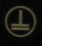
Others may recognize that symbol. The international standard for many years has been just 2 squares, one inside the other.

This may not be known to you, but the possibility is, that this amp. came from the US or elsewhere and and was simply ungrounded,
as most US appliances had been forever. That is to suggest it was not double insulated, just ungrounded and fitted with a standard US plug.
Bring it to the UK, fit a 13 amp UK plug, change the voltage tapping on the transformer (or fit a new one - as you find) and there you are -
a bodgied 230V conversion! 😱
Of course, that's just surmise but the signs may be there.
Last edited:
Reddish,
You are in the UK.
UK law applies.
You are NOT allowed to modify double insulated equipment.
In particular you are NOT allowed to convert it to "Earthed".
I do not recognise the symbol in post35
Double insulated symbol is two concentric squares.
It usually has the words "double insulated".
I am inclined to take heed of Ian's comment
a bodgied 230V conversion!
Last edited:
Thanks Ian, I'll start an new thread about that symbol.
The amp seems like it was made for the international market with it having the voltage selector on the back, I'll report back when I find out about that symbol.
The amp seems like it was made for the international market with it having the voltage selector on the back, I'll report back when I find out about that symbol.
That looks a bit like the symbol given by Wikipedia for Class I, but elsewhere on the web it says that there is no internationally recognised symbol for Class I.reddish75 said:I'm assuming that it should be double insulated, is the symbol in the pic attached the correct one for that?
Could it be that Mr. Bodger who previously messed with this amplifier did a DIY 'conversion' to Class II by simply omitting the earth wire?
You need to be sure what the amplifier is intended to be, and then return it to that state. This means that an earth lead is either required or prohibited. Making such a change would probably be legal as it could count as a repair.
Yes.................................return it to that state. This means that an earth lead is either required or prohibited. Making such a change would probably be legal as it could count as a repair.
- Status
- Not open for further replies.
- Home
- Amplifiers
- Solid State
- Twisting transformer secondary's