OS How far away are you from the Protection circuits etc. I am not pushing, just wondering...You have a lot on your plate and it has been a great edumuncation just looking and kibitzing and seeing the amp design process in real time. THANKS
Solid state speaker protection built into the OPS board would be a great idea. Bigun did exactly that with his TGM8 project and it worked great. I wonder if he would be prepared to collaborate with OS?
Nice idea if this solid state protection will be integrated to OPS board.
Please uncle OS if you would design it, considering more common available part forcthis portection.
Thank you
Please uncle OS if you would design it, considering more common available part forcthis portection.
Thank you
Once OS confirms with listening and burn in test that the OPS is totally viable then integrate a Bonsai or similar protection into the OPS and test that. Then and only then go for a group buy on 3 or 5 pair OPS board. This seems the most logical and if you do not want to include a protection circuit then just do not populate that portion of the board. All for one and one for all.😀 Like OS says choose the IPS of your choice...
Last edited:
Once OS confirms with listen and burn in test that the OPS is totally viable then integrate a Bonsai or similar protection into the OPS and test that. Then and only then go for a group buy on 3 or 5 pair OPS board. This seems the most logical and if you do not want to include a protection circuit then just do not populate that portion of the board. All for one and one for all.😀 Like OS says choose the IPS of your choice...
I'm all for the SS relay/DC-overcurrent circuit. I will design one.
But on the OPS board ... bad choice.
Ask me why ?
(lotsa reasons ....)
OS
OS,
I am assuming that what you are talking about with a protection scheme is an amplifier protection scheme and not a speaker protection implementation. I have earlier watch Esperando try and have a thread where he was doing a speaker and amplifier protection circuit and it got rather intense as far as the circuit and time requirements are concerned. I think he gave up trying to work on that in this type of forum, he has a rather limited amount of tolerance for some of the negative comments that some will always seem to add to a thread, we have only to look at Waly in the CFA thread to see what drives Christophe over the edge.
Keep it up you are doing great. Now we just need to see some doing first round testing of the real circuits to make sure there are no problems though I have high praise and expectations that there will only be minor changes at best to your multiple implementations here.
OS,
I am assuming that what you are talking about with a protection scheme is an amplifier protection scheme and not a speaker protection implementation. I have earlier watch Esperando try and have a thread where he was doing a speaker and amplifier protection circuit and it got rather intense as far as the circuit and time requirements are concerned. I think he gave up trying to work on that in this type of forum, he has a rather limited amount of tolerance for some of the negative comments that some will always seem to add to a thread, we have only to look at Waly in the CFA thread to see what drives Christophe over the edge.
Keep it up you are doing great. Now we just need to see some doing first round testing of the real circuits to make sure there are no problems though I have high praise and expectations that there will only be minor changes at best to your multiple implementations here.
Waly could make a Freight Train take a dirt road.
Bonsai and Christophe both have separate boards, but both of them do not have the ability to be used with the Higher output voltages of OS SlewMonster... Both would have to be modified to accommodate its higher output. It can be done. 😎
Solid state speaker protection built into the OPS board would be a great idea. Bigun did exactly that with his TGM8 project and it worked great. I wonder if he would be prepared to collaborate with OS?
Just read the whole thread ... (below) is the DC protect.
NOT enough ... circuit runs from a rail , no OC protect.
This is BIG amp ,
-separate 12-15v independant supply
-Complete control board with SS relay , DC , overcurrent ....
could even integrate a clip indicator and turn on delay.
PS - If I do design one , it will match the "anal" level of the OPS/IPS.
OS
Attachments
Waly could make a Freight Train take a dirt road.
Good to know, thank you 😀! Always ready to help.
UPC1237 ....
http://www.unisonic.com.tw/datasheet/UPC1237.pdf
A newer equivalant of the ta7317.
Even as the 7317 is easy to source ... so is the 1237.
They do essentially the same thing .
- DC offset (of course).
- AC turn on/off muting
- latching or auto reset on fault.
- input for overcurrent.
- relay driver OP could easily trigger that opto led/SS relay.
Why not build all this with discrete's ? Ha ! 😱
.... Try over 50 devices (1237 internals).
I KNOW all the diehards hate them chiiipppps ! , but these work.
The "overcurrent" could be a combo of clip detection and a averaging
circuit. Allowing occasional clipping but reacting to shorts.
On the 1237 , you could even trigger the "latching" feature on a
short or DC event. :😎
1237 also has separate AC and overcurrent pins ( multi input OR gate).
OS
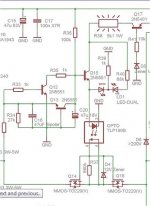
Why not use power supply with all needed protection included like this one. On the right side is a cap multiplier with over current and DC offset(loudspeaker protection) control. Even if one polarity of the power supply is down, other polarity will be switched off immediately.
I use something similar in my TT amp for years with no problem at all. It is different in the way that is not part of the amp PCB but power supply PCB. I wanted to make 200 W amp with that protection on the same amp board(Chris could remember it) but never did, to much project on go.
Damir
I use something similar in my TT amp for years with no problem at all. It is different in the way that is not part of the amp PCB but power supply PCB. I wanted to make 200 W amp with that protection on the same amp board(Chris could remember it) but never did, to much project on go.
Damir
Attachments
Why not use power supply with all needed protection included like this one. On the right side is a cap multiplier with over current and DC offset(loudspeaker protection) control. Even if one polarity of the power supply is down, other polarity will be switched off immediately.
I use something similar in my TT amp for years with no problem at all. It is different in the way that is not part of the amp PCB but power supply PCB. I wanted to make 200 W amp with that protection on the same amp board(Chris could remember it) but never did, to much project on go.
Damir
Or go even further , MOSFET switched rails.
I do see the 1237 solution used on a number of chip amp
kits and the larger LME48910 projects or "badger" class amps (below).
PS - nice amp ... drippin' with parts !
OS
Attachments

Last edited:
YES ...
Why not go all the way.
If you were to get a over current , or especially a DC event ...
Something is most likely wrong 🙁 ...
If the 1237 latches , why not shut down the amps OP AND
the rails. You would most likely be probing the insides of the amp
with a DMM and/or smelling the "magic smoke".
PS - collapsing the rails would minimize more "magic smoke" 😀
Another thought ... what about the fuses ?? If you had a DC
fault , one or more OP devices is most likely toast .... taking
out the fuse (after the 1237 event) , this would make the
rail switches redundant.
Audio purists would like a "fuseless setup" , but the SS rail
shutdown circuit would then have to be failsafe (nuclear plant 😀 ).
OS
Incidentally,
Jan Didden did a project using the UPC1237 part that was published in the Elektor 5/2008 rag. You can Google for it if anyone is interested. The relay that he used is especially interesting in that it is strictly for audio power switching purposes.
Amplimo LS Relay LSP-RELAY - Amplimo loudspeaker relay 24V - Europe Audio
Last edited:
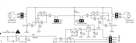
I think we need small transformer for power supply:
1. soft start
2. DC protection
3. Fan controller
4. Heat sink temperature monitor
5. Clipping indicator
6. Power ON/OFF using push button
Small microcontroller like ATmega8 can do the jobs.
1. soft start
2. DC protection
3. Fan controller
4. Heat sink temperature monitor
5. Clipping indicator
6. Power ON/OFF using push button
Small microcontroller like ATmega8 can do the jobs.
Bimo,
I don't have any trouble with your list except #1. We need the correct sized transformer, not to small and no wasteful in size. I bet you will get some flak about the fans but that to me is a non issue if they are quite.
I don't have any trouble with your list except #1. We need the correct sized transformer, not to small and no wasteful in size. I bet you will get some flak about the fans but that to me is a non issue if they are quite.
Bimo,
I don't have any trouble with your list except #1. We need the correct sized transformer, not to small and no wasteful in size. I bet you will get some flak about the fans but that to me is a non issue if they are quite.
We need 2 relays One for ON/OFF switch, other for soft start.
Fan is only turn ON when heat sink temperature reach a certain limit, say 50 degree Celsius and has variable speed related with heat sink temperature or we can use fuzzy logic controller. If heat sink temperature reach maximum temperature allowed, we can shut down the amplifier.
In normal listening and average room temperature, the fan should remain OFF.
Last edited:
One key protection circuit implementation decision is whether to include:
output signal .does not closely match. input signal detection
Once the commitment is made to use opamps for a DC servo, and include a separate "fast start" well regulated +/- 15 volt power supply, many designs leverage this investment to provide more complete protection like: (construct your own simple or Heroic flowchart here)
DETECT THESE FAULTS:
1) large DC voltage appears on output
2) output terminals have a short circuit
3) output signal .does not closely match. input signal (this covers output clipping and output shorts)
4) "start fan" warm temperature detection on output transistors
5) switch power off high temperature detection on output transistors
USE FAULT DETECTION TO CONTROL:
1) input "thump" turn on protection relay/switch
2) slow start main power supply "safe" sense WITH full-power switch-on control .OR. main AC switch off control
3) speaker destruction protection
a) mechanical relay or solid state MOS switch
b) switch in series with speaker, or switch connecting low R shunt to ground
4) quick AC disconnect power down
5) any cooling fans
- Home
- Amplifiers
- Solid State
- Slewmaster - CFA vs. VFA "Rumble"