I was looking for diodes with similar specs as Dadod suggested, but for an other application. (2 diodes in anti parallel over the pos and neg input of a jfet complementary input stage to keep dissipation power of the jfets within limits with high input signals during clipping)
https://www.fairchildsemi.com/ds/FJ/FJH1100.pdf
To low voltage, but very low leakage. The one OS suggested is very similar to BAV21, same leakage, same capacitance, no good.
Vostro,
Your tests were made at more than 20 kHz.
How do the clipped signals look at more audible frequencies ?
Your tests were made at more than 20 kHz.
How do the clipped signals look at more audible frequencies ?
Tried R18 and R38 at 1k, output the same
tried anti-parallel 1N4148 diodes Q12,Q3collector, output the same,
or should it be Q2,Q1 collectors ?
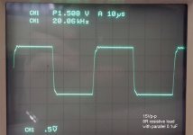
At 20khz 100Vp-p output SR=50V/us if I measured correctly.
Tried 100nF cap parallel to 8R resistive load at 20kHz, is this test important ?
Is ringing allowed in this test or should it result in clean square wave on output
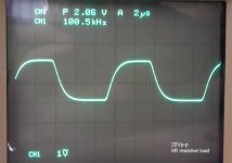
Lol put 100kHz square wave input, while talking at same time to friend, turned amplitude close to or maybe into clipping, and oscilloscope waveform goes flat line.
Blew two output transistor 1 NPN and 1 PNP, desoldered them and working again.
posted pictures below of waveforms.
Regards
tried anti-parallel 1N4148 diodes Q12,Q3collector, output the same,
or should it be Q2,Q1 collectors ?
At 20khz 100Vp-p output SR=50V/us if I measured correctly.
Tried 100nF cap parallel to 8R resistive load at 20kHz, is this test important ?
Is ringing allowed in this test or should it result in clean square wave on output
Lol put 100kHz square wave input, while talking at same time to friend, turned amplitude close to or maybe into clipping, and oscilloscope waveform goes flat line.
Blew two output transistor 1 NPN and 1 PNP, desoldered them and working again.
posted pictures below of waveforms.
Regards
Attachments
I was looking for diodes with similar specs as Dadod suggested, but for an other application. (2 diodes in anti parallel over the pos and neg input of a jfet complementary input stage to keep dissipation power of the jfets within limits with high input signals during clipping)
https://www.fairchildsemi.com/ds/FJ/FJH1100.pdf
Those are OUTRAGEOUSLY EXPENSIVE! Although they do look like very good candidates, I don't think anyone can afford those, at least not the regular diyer who's not rich.
However I would suggest taking a look at the BAS34. Anyone has a good spice model for that one?
And it's easy to put 2 diodes in series, to at least divide the capacitance by 2.
To low voltage, but very low leakage. The one OS suggested is very similar to BAV21, same leakage, same capacitance, no good.
I must have a spice model issue. As I tried both the 1N4148 and BAV21 on a vas and the BAV21 performed perfectly while the 4148 was a disaster. That 4148 model is from ltspice's library, so perhaps it's not so good.
I think it's worth taking a look at the BAS34 though. It's not expensive, the capacitance is half that of the 4148/914 and also lower than the bav21.
The reverse capacitance of the diode is important - should be very low.
Which one do you favor? What do you think about 2 in series? At least that's a step in the right direction...
The BAV21 (which is what I've used for the VAS clamps in my e-amp) quote a max reverse capacitance in the data sheet of 5pF, but if you look at the graph, the maximum shows as 1.4pF, and by 10V or so, its close to 1pF.
As a semcinductor marketing guy, I suspect that the design of the diode supports the graph, but in high volume production, testing reverse capacitance is not that easy, so they put in a limiting value of 5pF (Diodes would be batch tested periodically to ensure they met their published specs as part of QC). Obviously during development, they would have characterized the diode - which is where the graph comes from.
http://www.nxp.com/documents/data_sheet/BAV20.pdf
(data sheet covers BAV20 and BAV21)
My sims show a 2ppm penalty for using a VAS baker clamp - i.e. from ~8ppm to about 10ppm at close to full power 20 kHz.
Bottom line - I would not worry about it - stick them in and focus on other areas of your design where you can make more important improvements.
For back to back diodes used to clamp e.g. a mirror or the LTP collectors, one option is to look at the ultra low capacitance ESD diodes (unfortunetely always SMD in order to keep lead inductances low).
Here is an example of the type of diode I am talking about for this type of back to back LTP clamp http://www.nxp.com/documents/data_sheet/NUP1301.pdf
Last edited:
The BAV21 (which is what I've used for the VAS clamps in my e-amp) quote a max reverse capacitance in the data sheet of 5pF, but if you look at the graph, the maximum shows as 1.4pF, and by 10V or so, its close to 1pF.
It's clear that when I compared the effects in simulations between the ltspice provided 1N4148 model and the BAV21 model that I found, the bav was a clear winner. But then there is likely something odd about the models though.
I didn't have the datasheet from philips on the bav, so it's good to compare. I was using the bav datasheet from fairchild, which doesn't have the graph for the capacitance.
The bav21 model that I have seems to use 5pf for capacitance. But I could be mistaken, since I don't really know enough about the spice parameters in models. As far as I understand, the parameter in question is Cjo in the 1N4148 model in ltspice and that model is from onsemi, with a Cjo at 4p.
To make realistic comparison, it is necessary to make sure the models we use are coherent on this. From what I see in the models, I think the bav may have that capacitance overstated then, as it uses the maximum value.
If I look at those Cjo parameters, then the 4148 is at 4p while the bav at 5p. Which makes no sense as the effect is reversed in simulations. There must also be something else acting.
While digging in datasheets, I can see that other types such as the 1N916/1N4448 have half the capacitance compared to the 914/4148. That's already much better. But I think the BAS34 looks even better.
My sims show a 2ppm penalty for using a VAS baker clamp - i.e. from ~8ppm to about 10ppm at close to full power 20 kHz.
I saw similar results, and using the bav21 on the ltp collectors doesn't have any adverse effect compared to the important one using the 4148.
The thing is, the diodes see a huge voltage swing when used on the vas, but not very much when on the ltp legs. With the leakage currents being so low at low voltage, it seems using the clamps on the ltp imposes mostly taking a look at capacitance and not so much leakage.
Bottom line - I would not worry about it - stick them in and focus on other areas of your design where you can make more important improvements.
I agree, carefully chosen, their impact is fairly small compared to the benefits.
I have a design where the output stage as a higher than unity gain (close to 2), which makes the vas swing a lot less, and I am using clamps on both the ltp and the vas, while keeping the thd below 10ppm on 4ohms at full power @ 20khz. So this is a fine trade off.
For back to back diodes used to clamp e.g. a mirror or the LTP collectors, one option is to look at the ultra low capacitance ESD diodes (unfortunetely always SMD in order to keep lead inductances low).
Here is an example of the type of diode I am talking about for this type of back to back LTP clamp http://www.nxp.com/documents/data_sheet/NUP1301.pdf
Since I can't make use of any smd, my choices are more limited. I see that this one is rather low priced, so for those able to solder smds, it's a fine choice.
Regarding back to back diodes, do you mean 2 of them in opposition (parallel)?
I added 4 diodes in parallel with the caps in the feedback return to ground on my design. Using the ltspice provided 1N4148. In that location the capacitance isn't any issue, with the very large capacitance in parallel already there. But what about leakage? Is this an issue there? Should lower leakage types be mandated in that spot?
Back to back - yes I mean in 'anti parallel arrangement'
For the leakage issue, I cannot comment. I am seing diode leakage of a few nA at high voltage and wonder if the error due to that is not completely swamped by other factors.
For the leakage issue, I cannot comment. I am seing diode leakage of a few nA at high voltage and wonder if the error due to that is not completely swamped by other factors.
On Monday I'll solder tulip pins where diode clamp goes and will switch in and out the diode and see if I notice a difference in sound, I'm not expecting to notice a difference, I feel much more at peace with the diode in circuit. I've never really considered the 1N4148 for this purpose on +/-63Vdc rails.
Bonsai, with my circuit in post 1/2 where would you place the diodes on Ltp, if I got them cascaded?
By the way the reason I choose bav21 is because you used it in your amp, I really enjoy the Wright up you do on your amps, a great read.
Bonsai, with my circuit in post 1/2 where would you place the diodes on Ltp, if I got them cascaded?
By the way the reason I choose bav21 is because you used it in your amp, I really enjoy the Wright up you do on your amps, a great read.
I am wondering about the behavior of ordinary vi limiters (think of the likes as found in the leach).
When the limiter is activating, shouldn't the proper behavior be looking somewhat like clipping?
When the limiter is activating, shouldn't the proper behavior be looking somewhat like clipping?
Hope this circuit has been implemented. How did you solve the probem of clipping?The circuit
- Home
- Amplifiers
- Solid State
- bad clipping