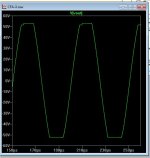
CFA clipping ...
Below 1 is VSSA clipping behavior . Member Bimo also reported the input
pair getting quite warm during high power /clipping.
I think his build is a hybrid VSSA/hawksford. No smoking amp , but CFA's
tend to be "sticky" .... but don't exhibit saturation like a VFA.
NAF built the NADservo (NX) .. hasn't reported any hot devices.
(below 2 ) it also sticks ... but not as much.
3 different VAS pairs (models ) show some sticking, but generally it
is of a much smaller magnitude and very symmetrical. The real amps
also show minimal "bad behavior" and never let out the "magic smoke"
PS - the symmetrical VFA leach is much worse and both saturates AND sticks
with the same VAS as the VSSA .... the topology must determine this behavior.
OS
Attachments
To clip nicely or to not clip at all?
yes, I understand. My position is that the amp in question does not misbehave itself during clipping. Clearly, that isnt the case for all topologies and operation. Now take your best behaved amplifier and clip it... do the FFT on it for the harmonics produced. As far as listening is concerned, it isnt a whole lot better than a poorly behaved clip.
What topology does better when it clips and how to produce the lowest/fewest harmonics when clipping - soft clipping - or prevent clipping from occurring via design. Otherwise- its clipping indicators or just bigger amps and higher efficient speakers and/or bi-tri amping.
THx-RNMarsh
This still has some 'overhang' Pavel, but I would agree its better than the single ended blameless design in this regard.
I used diodes on my symetrical e-Amp and distortion is <10ppm 20 kHz at 180W. You need to use a low capacitance diode. Without the diode, I get another 2-3ppm lower distortion - not a problem in the big scheme of things.
Having said that, I agree with OS's proposals, altthough I like to run my VAS at about 20mA in a triple 😉
Interestingly, I've noticed that this is much less of a problem on CFA's - I commented about it in the sx-Amp write-up.
Richard, now you see why we think how an amp behaves when it clips is important!
yes, I understand. My position is that the amp in question does not misbehave itself during clipping. Clearly, that isnt the case for all topologies and operation. Now take your best behaved amplifier and clip it... do the FFT on it for the harmonics produced. As far as listening is concerned, it isnt a whole lot better than a poorly behaved clip.
What topology does better when it clips and how to produce the lowest/fewest harmonics when clipping - soft clipping - or prevent clipping from occurring via design. Otherwise- its clipping indicators or just bigger amps and higher efficient speakers and/or bi-tri amping.
THx-RNMarsh
Using Harmon/Crown/JBL as a source for what power is needed in different venues --> Using typical room size and speaker efficiency and listening distances etal:
* Nearfield monitoring: 25W for 85dB spl average (with 15 dB peaks); 250W for 95dB spl averge (with 15dB peaks)
* Home Stereo: 150W for 85dB average (with 15dB peaks); 1500W for 95dB average (with 15dB peaks).
ETC
You can play with the numbers, if you want. Different effeciency speakers, larger volume home listening room, higher peak-average ratio, etc. But, all-in-All, the power needed is a lot more than most people think to prevent clipping. We should be designing At least 150W -250W home amps.
THx-RNMarsh
Last edited:
I think the magic rule with clipping & saturation is:-
The more excess current you pump into the base of a transistor, the bigger the problem you have to suck it out. Clearly on a lot of these designs, the loop is far quicker than the the ability to suck the excess charge out. So, where possible
1. minimize excess current into the transistor base
2. use devices which show good recovery characteristics - for example, MJE340/350 are not good, and neither is the 2N550/1
3. If you must, apply a Baker clamp (I typically get about 2-3ppm degradation on 10ppm overall - not an issue in my view)
4. Watch out for mirrors - if you run high LTP tail current they can also get ugly - mitigate with diode clamps.
+1Whst about the 47 ohm resistors in the CCS bases? I would raise these as well.
R18 in particular should be raised to maybe 470R or 1K. As it is, the reference voltage across the two diodes will collapse badly during positive clipping, and recovery will be slightly delayed by the capacitor across them.
I don't see a problem with R38 though.
What about clipping amp like http://www.diyaudio.com/forums/solid-state/248105-slewmaster-cfa-vs-vfa-rumble-59.html#post3834503
May be, I will build it for my new IPS (OS style 😀).
May be, I will build it for my new IPS (OS style 😀).
So, in this discussion of over driven driver stage causing sticking, what is the result of running the input/vas/driver stages from significantly higher voltage than the final output stage, such that under moderate to severe overdrive, only the final output stage actually clips ?.
Further developments might include variable supplies for the final output stage, allowing lower quiescent and active dissipation when running lower playback levels, like TV or radio/bgm.
A Rod Elliot style distortion/clip indicator would enable suitable/optimal setting of output stage supply voltage.
Dan.
For example TDA7294 has separated pins for output and signal stages....has anybody tried different/variable supplies for output and signal stages ?.


As per the clipping indicator discussion going on elsewhere, this might be an interesting way of gauging the sonic impact of variable degrees of clipping for a given signal level.
Ditto gauging the sonic impact of differing combos of power transformer capability and reservoir caps.
How bad is a 'high headroom' (ie, small transformer) output stage supply vs a more capable output stage supply within the condition that the input/driver stages run from clean/stable supplies ?.
Dan.
Last edited:
So, in this discussion of over driven driver stage causing sticking, what is the result of running the input/vas/driver stages from significantly higher voltage than the final output stage, such that under moderate to severe overdrive, only the final output stage actually clips ?.
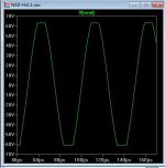
Clips like this, then. Anyway, even with same rails there should be no problem with clipping. I like 'strong' VAS, I use VAS idle current up to 30mA with on-demand ability.
Attachments

In this situation , Can you hear the diode , degraded sonics...?Not if it is a VERY low reverse leakage type.
pA/nA leakage can be corrected by NFB - uA can not be.
But , even the best diodes will add 5-10ppm at moderate amplitude -
a "tradeoff".
OS
Using Harmon/Crown/JBL as a source for what power is needed in different venues --> Using typical room size and speaker efficiency and listening distances etal:
* Nearfield monitoring: 25W for 85dB spl average (with 15 dB peaks); 250W for 95dB spl averge (with 15dB peaks)
* Home Stereo: 150W for 85dB average (with 15dB peaks); 1500W for 95dB average (with 15dB peaks).
ETC
You can play with the numbers, if you want. Different effeciency speakers, larger volume home listening room, higher peak-average ratio, etc. But, all-in-All, the power needed is a lot more than most people think to prevent clipping. We should be designing At least 150W -250W home amps.
THx-RNMarsh
Agree , it takes a lot more than most people think , some recordings exceed 20db on peaks.
Clips like this, then. Anyway, even with same rails there should be no problem with clipping. I like 'strong' VAS, I use VAS idle current up to 30mA with on-demand ability.
Agree with Pavel on this, still wondering if there is better results to get from a slightly higher regulated voltage for VAS.?
Last edited:
Sure, 'natural' sounds' (acoustical/orchestral) recordings might/will achieve this, but rock/pop etc mostly won't.Agree , it takes a lot more than most people think , some recordings exceed 20db on peaks.
Of course good rock'n'roll turned up can be fun too (more reasons for big amplifiers) 😉.
Dan.
Yup, that's what I'm asking.Agree with Pavel on this, still wondering if there is better results to get from a slightly higher regulated voltage for VAS.?
Dan.
Pity I only get about an hour after work to get to experiment on my amp, work is very busy at the moment.
Didn't note before but Cf1 is not populated.
Some things tried that did not solve the waveform from post 1 (with D8 out of circuit)
Increased R20 to 27R, no change
Reduced vas ccs current R4=100R , Iq 6.5mA, no change
Short out R17, no change
Changed R16 from 820R to 4k7, no change, maybe more unstable
Next will change R18, R38 to 1k and report back.
I didn't check how the above changes effect the waveform with the diode clamp in circuit.
Regards
Not if it is a VERY low reverse leakage type.
pA/nA leakage can be corrected by NFB - uA can not be.
But , even the best diodes will add 5-10ppm at moderate amplitude -
a "tradeoff".
OS
It is not only reverse leakage current but capacitance(very non linear) that increase distortion. Standard 1N4148 has 4 pF, MMSD4148 has .64 pF, and that capacitance added to the MIller or even worst, if TMC was used it will disrupt compensation as it bridged TMC. I case I simulated, THD20k with no diode was 1.6 ppm and with 1N4148 jump to 67 ppm,and with MMSD4148 to 7.8 ppm. Diode in that position is NO NO. BAV21 has 5 pF, even worst then ordinary 1N4148 and with higher leakage current.
What diode to use for Backer clamp as 1N4148 is 100 V only, and BAV21 has to high leakage current??
BR Damir
So, in this discussion of over driven driver stage causing sticking, what is the result of running the input/vas/driver stages from significantly higher voltage than the final output stage, such that under moderate to severe overdrive, only the final output stage actually clips ?.
Further developments might include variable supplies for the final output stage, allowing lower quiescent and active dissipation when running lower playback levels, like TV or radio/bgm.
A Rod Elliot style distortion/clip indicator would enable suitable/optimal setting of output stage supply voltage.
Dan.
That's plan "B" for my slewmaster series. The setup would be for the OPS
to run at 60V rails with a "boosted" 75+ V regulated supply for the IPS.
"boosted" Jumpers are already there for all 3 of my OPS's ... 😎
OS
It is not only reverse leakage current but capacitance(very non linear) that increase distortion. Standard 1N4148 has 4 pF, MMSD4148 has .64 pF, and that capacitance added to the MIller or even worst, if TMC was used it will disrupt compensation as it bridged TMC. I case I simulated, THD20k with no diode was 1.6 ppm and with 1N4148 jump to 67 ppm,and with MMSD4148 to 7.8 ppm. Diode in that position is NO NO. BAV21 has 5 pF, even worst then ordinary 1N4148 and with higher leakage current.
What diode to use for Backer clamp as 1N4148 is 100 V only, and BAV21 has to high leakage current??
BR Damir
Well , we just have to find a better diode .. eh ? 😛
http://www.fairchildsemi.com/ds/1N/1N3070.pdf
200V / .1ua leakage /5pF/ 50ns recovery ... mouser has 45K of em' .
OS
I was looking for diodes with similar specs as Dadod suggested, but for an other application. (2 diodes in anti parallel over the pos and neg input of a jfet complementary input stage to keep dissipation power of the jfets within limits with high input signals during clipping)
https://www.fairchildsemi.com/ds/FJ/FJH1100.pdf
https://www.fairchildsemi.com/ds/FJ/FJH1100.pdf
- Home
- Amplifiers
- Solid State
- bad clipping