I just ran the #'s on djk's PPSL with Kappa LF2's...
You can't sim that fully with Hornresp, there's going to be line resonances caused by the long and skinny rear chamber that Hornresp won't show since it can't simulate the rear chamber shape properly. I could do it with different software if you want a more accurate sim and if you've got dimensions of the rear chamber.
WRT the rear volume: Would those resonances not be the same as any center ported double 18" cab that's tuned low?
This cab's internal dimensions are smaller than most double woofer pro cabs.
This cab's internal dimensions are smaller than most double woofer pro cabs.
"I found that very hard to believe so I simulated it."
So what, I have measured actual PPSL loudspeakers.
The EV published graphs for theirs showed no such peak either.
How does the sim take into consideration the magnet of one driver shoved into the front of the other driver, the irregular cavity, and reduced volume of same?
Perhaps you could be wrong?
"and can also be used to make the cavity physically smaller (less wasted space). "
I've looked into that, and I come up with no real saving in terms of wasted space, and a much harder build.
My current versions were made simple enough for weekend wood-butchers to build, and get a solid cabinet, and with a low-waste cutting plan. I've seen them built successfully by people that had no previous woodworking experience.
PUKK-212
This might be the smallest cabinet in the PUKK range but it is still considered to be a wolf in sheeps clothing. Looking small and cute, it will surprise everyone in its proximity. Low frequency limit is down at 40Hz(-3dB) and the sound pressure level can keep up with 18" subwoofers.
PUKK-215
The middle brother sitting in between 218 and 212 gets the best parts from both cabinets. Still nice and practical, this light weight cabinet is a joy to move around but it delivers ground shaking bass down to 35 Hz (-3dB) with sound pressure comparable to common double 18" cabinets in the market.
PUKK-218
After three of these beasts might have caused a volcano eruption in Iceland when they were being tested outside for the first time there is little left to say about this monster.
Check out the frequency response with crossover applied (it's an LR24, so it's -6dB at the crossover point, looks like the double 18 version is good to cross at 150hz on this graph).
http://www.ohm.co.uk/download/DATASHEET/PUKK-218%20Datasheet.pdf
So what, I have measured actual PPSL loudspeakers.
The EV published graphs for theirs showed no such peak either.
How does the sim take into consideration the magnet of one driver shoved into the front of the other driver, the irregular cavity, and reduced volume of same?
Perhaps you could be wrong?
"and can also be used to make the cavity physically smaller (less wasted space). "
I've looked into that, and I come up with no real saving in terms of wasted space, and a much harder build.
My current versions were made simple enough for weekend wood-butchers to build, and get a solid cabinet, and with a low-waste cutting plan. I've seen them built successfully by people that had no previous woodworking experience.
An externally hosted image should be here but it was not working when we last tested it.
PUKK-212
This might be the smallest cabinet in the PUKK range but it is still considered to be a wolf in sheeps clothing. Looking small and cute, it will surprise everyone in its proximity. Low frequency limit is down at 40Hz(-3dB) and the sound pressure level can keep up with 18" subwoofers.
PUKK-215
The middle brother sitting in between 218 and 212 gets the best parts from both cabinets. Still nice and practical, this light weight cabinet is a joy to move around but it delivers ground shaking bass down to 35 Hz (-3dB) with sound pressure comparable to common double 18" cabinets in the market.
PUKK-218
After three of these beasts might have caused a volcano eruption in Iceland when they were being tested outside for the first time there is little left to say about this monster.
An externally hosted image should be here but it was not working when we last tested it.
Check out the frequency response with crossover applied (it's an LR24, so it's -6dB at the crossover point, looks like the double 18 version is good to cross at 150hz on this graph).
http://www.ohm.co.uk/download/DATASHEET/PUKK-218%20Datasheet.pdf
Last edited:
WRT the rear volume: Would those resonances not be the same as any center ported double 18" cab that's tuned low?
I don't know what you mean, but the rear chamber is long and skinny like a transmission line, it can't be simulated properly as a helmholtz resonator.
Also, I just noticed that your Hornresp sim has an extra segment with a length of .1 cm and an area of 4954.83 cm2. I'm not sure why you put that there but it isn't correct and the sim looks much different without it.
Awhile ago I noticed some people were attempting to simulate the baffle face with a segment like this, if that's what you are trying to do, it isn't accurate and it shouldn't be there.
Perhaps you could be wrong?
It's been known to happen but in this case I doubt it. If you simulate what you built accurately the measurement should be very close to the sim. Sims don't lie about cavity resonances.
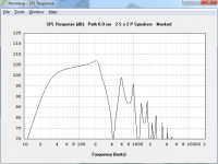
Why does the response in this picture drop like a rock at 100 hz? Let's see it with no filters. If it needs a steep filter at a low frequency, a ported box seems like a much better option.
The page you linked to recommends a 24db/oct LPF at 90 hz. It needs the filter to be at a low frequency to counter the rising response from the resonance.
A 15 - 18 inch cavity is going to cause a resonance somewhere between 150 - 200 hz approximately. A LPF like the one recommended in the OHM link will hide that resonance and it will look fairly benign at first glance but the result will be an abnormal knee in the curve in that resonance area when you look closer, and it will be hard to properly integrate the mains. Try it in a crossover simulator and you'll see what I mean, it will be difficult to sum the sub and mains to flat response with good phase tracking.
It's clear to see in the graph you posted and in the measurement on the page you linked to, it shows a gradual drop from 90 - ~150 hz and then it drops like a rock. Below 90 hz the LPF is acting to counter the rising response caused by the resonance.
You can see it in a sim too, here's NEO Dan's sim of the PPSL (without the superfluous .1 cm segment) with a 24 db/oct LPF at 90 hz. Same gradual drop from 90 - ~170 hz and then it drops like a rock. That's not what it's supposed to look like. If you start with a flat response you won't have that clearly defined knee an octave above the crossover point. It's not the end of the world, it is manageable but not with textbook filters. It's still my opinion that driver distortion is a better tradeoff than this type of response. To be clear, this is a walk in the park compared to crossing over most horns and tapped horns, but those alignments have CLEAR benefits over a ported box and are worth the trouble, unlike PPSL vs regular ported box.
An externally hosted image should be here but it was not working when we last tested it.
Last edited:
What is it that you need clarification on?I don't know what you mean, but the rear chamber is long and skinny like a transmission line, it can't be simulated properly as a helmholtz resonator.
Also, I just noticed that your Hornresp sim has an extra segment with a length of .1 cm and an area of 4954.83 cm2. I'm not sure why you put that there but it isn't correct and the sim looks much different without it.
Awhile ago I noticed some people were attempting to simulate the baffle face with a segment like this, if that's what you are trying to do, it isn't accurate and it shouldn't be there.
1. the rear volume is not simulated as a transmission line, TH, or Helmoholtz resonator. It's a rear volume with a port, it's very simple.
The baffle is in the sim because it exists in real life, the difference is not significant IMO. But since the system is not mounted or used in an infinite baffle it is logical to account for it in the model when Hornresp allows.
Awhile ago I noticed you began posting regularly in this subforum. Have you ever noticed that you spend a lot of time telling others, whom may or may not have extensive experience in the field that what they are doing, or what they share of their experience is just wrong? My advice - don't be "that guy". 🙂
What is it that you need clarification on?
1. the rear volume is not simulated as a transmission line, TH, or Helmoholtz resonator. It's a rear volume with a port, it's very simple.
Long, skinny enclosed spaces need to be simulated as long, skinny enclosed spaces with features like drivers and ports in the correct location or they are not simulated correctly. Try simulating a transmission line in WinISD and see if it gives accurate results.
The baffle is in the sim because it exists in real life, the difference is not significant IMO. But since the system is not mounted or used in an infinite baffle it is logical to account for it in the model when Hornresp allows.
Hornresp can't simulate baffles. You need another program for that, they do exist. The difference between your sim with and without a .1 cm segment is very significant.
Awhile ago I noticed you began posting regularly in this subforum. Have you ever noticed that you spend a lot of time telling others, whom may or may not have extensive experience in the field that what they are doing, or what they share of their experience is just wrong? My advice - don't be "that guy". 🙂
I've been posting here for 8 years. I'm trying to help. If you can prove that anything I say is wrong I encourage you to correct me, I might learn something and I'm very happy when that happens and I do admit when I'm wrong. But bring your A game, I'm serious about this stuff and I try not to be wrong. When I point out mistakes, I seriously believe they are important and people can choose to learn from that or ignore it. Having said that, I am considering taking a break from the forums, it is tiresome trying to help people and being told to shut up, which is happening about weekly lately. This is a place to learn and share, not social networking.
Last edited:
Being wrong etc !
Just for the record, i don't suppose many people actually like being wrong. But having wrongs pointed out & corrected is often how we learn. So i for one don't mind a bit. Naturally courtesy helps in swallowing the pill 😉
I would be sad to see just a guy not providing us with his knowledge & advice/sims/designs etc anymore, & i expect others would too.
So don't get upset about it, instead get wiser 🙂
Im a bit lost now with all the posts and comments .. Im sorry
But can i know clearly what driers for sub and how many with the link to buy both , same thing with the midbass ...
Please
Thanks 🙂)))
But can i know clearly what driers for sub and how many with the link to buy both , same thing with the midbass ...
Please
Thanks 🙂)))
All your sims do not agree with the measured results.
I have built double 18 PPSL and successfully crossed them at 250hz.
Les Hudson has done the same with dual 15 and found them useable to 400hz.
Electrovoice has build a double 15 PPSL crossed at 800hz. It gets a bit rough above 400hz, but does'nt look anything like the Hornresp sims.
Conclusion
Hornresp can't sim the plenum with the drivers breaking the space into an irregular shape in an accurate fashion.
As me which I believe, the speaker in front of me, or your inaccurate sim?
"There is no carity resonance to speak of in the units I have built. There is a port resonance that is way out of band. If you face both woofers into the slot there is a cavity resonance based on the depth of the slot, and it is generally out of band as well. I did have a fellow deliberately run one that way because he liked the cavity resonance and extra distortion (no accounting for taste I guess)."
" it is tiresome trying to help people and being told to shut up,"
When you disagree with the measured results, and don't bother reading what is posted, you deserve all the grief you get in return.
While I may have wished you would hold your tongue, you will note that I never said so.
" it is tiresome trying to help people and being told to shut up,"
When you disagree with the measured results, and don't bother reading what is posted, you deserve all the grief you get in return.
While I may have wished you would hold your tongue, you will note that I never said so.
When you disagree with the measured results, and don't bother reading what is posted, you deserve all the grief you get in return.
I read everything that was posted, you've posted twice now that there is a cavity resonance based on cavity depth, it's even bolded. That's exactly what I said and what I showed in the sim.
I'm not disagreeing with measured results, the measurements agree with me. The OHM link recommends a steep crossover at a low frequency to counter the rising response caused by the resonance, and as expected, as shown in their measurement the acoustic crossover point is higher than the electric crossover point. I showed this in a sim as well. Having a big resonance very near the crossover point puts an unnatural knee in the response, even when a LPF is applied. Everything I said is clearly shown in my sims and your own measurements and links. None of the measurements shown are shown without a LPF specifically because you would clearly see the resonance. Even with the LPF you can still see the unnatural knee in the response.
I don't agree with you and it doesn't appear you have any evidence (unfiltered response measurements) that would disagree with the sims I showed. You claim other people (or companies) choose to use an inappropriately high crossover frequency and have rough response above 400 hz, which also agrees with my sim, but the resonance problem is much lower and will mess up integration with the mains. This is all clearly evident in the measurement you posted and in the OHM paper.
Disagree if you like but post some proof, I've already proven my case. IMO it's just common sense that an 18 inch deep cavity is going to cause problems. Simulations agree, measurements agree. You and I can agree to disagree, I have no desire to talk about PPSL anymore.
You sir, are being obnoxious (perhaps you don't mean to be?).
I have been awaiting your response to my observation that the peak is there when both drivers fire into the plenum, and that it is not there when one driver is reversed.
Build it or not, as you see fit.
I have been awaiting your response to my observation that the peak is there when both drivers fire into the plenum, and that it is not there when one driver is reversed.
Build it or not, as you see fit.
Last edited:
You sir, are being obnoxious (perhaps you don't mean to be?).
Read it however you like. I posted a bunch of information that you haven't responded to. I spent a couple hours looking for an unfiltered PPSL measurement, couldn't find anything anywhere.
The effect of a driver basket in the slot is a bit of reduced volume in the slot, a bit different slot shape and a very small amount of damping due to the cone that's not infinitely rigid. It isn't going to make the resonance disappear and it isn't going to drastically push it up in frequency.
I believe modest reduction in 2nd order distortion does not achieve the benefits claimed by PPSL proponents, I believe they like the effect of the cavity resonance.
I'm not ever going to build one of these and I'm not encouraging you to stop building them, so this is probably a good place to stop. I really don't want to discuss PPSL anymore. I've got better things to do, I'm sure you do too.
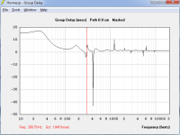
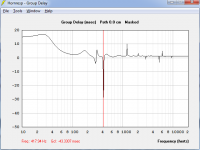
In Hornresp the TH18 type box has a BIG group delay peak ~120Hz, and it's actually there in real life, but not nearly as bad as the model.
OTOH the PPSL has a small rise at 174Hz that will come out in the wash, the first audible wrinkle is at 300Hz, and a GNARLY looking group delay notch ~400Hz that likely sounds like an angry rabid squirrel. Sure, that's not going away but it's so far out of band that it's not worth arguing about. TH with a similar FB do not have better(=less audible) group delay performance. If this was such a problem God would not have said that on the seventh day, thou shalt come gather at my house and listen to my $$$,$$$ DSL system.
If you want to vent your frustrations about the travesty's of audio design find a car audio forum or a bo$e thread somewhere - else.
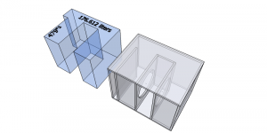
You seem to have no end to the energy you are willing to expend to prove you've got the bigger 🙄, why don't you do something interesting/useful and use the Sketchup CAD model I provided and show us all your "A game" BEM modeling skills??? I seem to recall you asking for the dimensions...
Pass the collection plate!
Thank you - drive thru. 😀
OTOH the PPSL has a small rise at 174Hz that will come out in the wash, the first audible wrinkle is at 300Hz, and a GNARLY looking group delay notch ~400Hz that likely sounds like an angry rabid squirrel. Sure, that's not going away but it's so far out of band that it's not worth arguing about. TH with a similar FB do not have better(=less audible) group delay performance. If this was such a problem God would not have said that on the seventh day, thou shalt come gather at my house and listen to my $$$,$$$ DSL system.
If you want to vent your frustrations about the travesty's of audio design find a car audio forum or a bo$e thread somewhere - else.
You seem to have no end to the energy you are willing to expend to prove you've got the bigger 🙄, why don't you do something interesting/useful and use the Sketchup CAD model I provided and show us all your "A game" BEM modeling skills??? I seem to recall you asking for the dimensions...
Pass the collection plate!
Thank you - drive thru. 😀
Attachments

If you want to vent your frustrations about the travesty's of audio design find a car audio forum or a bo$e thread somewhere - else.
You seem to have no end to the energy you are willing to expend to prove you've got the bigger 🙄,
Yeah, that's enough. I'm not going to post in this thread anymore. But please don't mistake my lack of response as a sign that I doubt anything I've posted here, or that I agree with anything you or djk are posting.
yup. I'm amazed at the people who bash a ppsl who have never built nor heard one.
To me they sound like the velodyne subs with their distortion reducing circuitry, but without the $2k price tag.
Norman
To me they sound like the velodyne subs with their distortion reducing circuitry, but without the $2k price tag.
Norman
"I believe modest reduction in 2nd order distortion does not achieve the benefits claimed by PPSL proponents, I believe they like the effect of the cavity resonance."
Art Welter measured as much as 30dB reduction in 2nd harmonic, and 20dB reduction in 4th harmonic at high power using LAB 12 drivers in a co-planar mounted pair.
I guess a 1000:1 reduction is modest?
Art Welter measured as much as 30dB reduction in 2nd harmonic, and 20dB reduction in 4th harmonic at high power using LAB 12 drivers in a co-planar mounted pair.
I guess a 1000:1 reduction is modest?
- Status
- Not open for further replies.
- Home
- Loudspeakers
- Subwoofers
- Professional subwoofer