Is the easiest no pop solution to tie a slow charge RC circuit to pull up resistor on the mute pin?
Is the easiest no pop solution to tie a slow charge RC circuit to pull up resistor on the mute pin?
No. The amp is muted when the MUTE pin is pulled high. The easiest solution is to put a 10µF-100µF capacitor between the SDZ pin and GND after the current limiting 100Kohm resistor. That gives a 0.1s to 1s delay on the turn on depending on capacitor size and supply voltage.
No. The amp is muted when the MUTE pin is pulled high. The easiest solution is to put a 10µF-100µF capacitor between the SDZ pin and GND after the current limiting 100Kohm resistor. That gives a 0.1s to 1s delay on the turn on depending on capacitor size and supply voltage.
Here?
An externally hosted image should be here but it was not working when we last tested it.
I am not an expert, but the one 100k pot (Valab stepped attentuator) I have used (on the YJ red board, 2.0) is the only one to ever pick up noise in about a dozen different amps, using 20k to 50k pots. Admittedly, this is in a very noisy environment.
Stepped attenuators are new to me, so I do not know if it was the basic design or the value.
When Valab gets more smd resistors I will order their 20k model (early March, according to an email) because I really like the sound of their stepped attenuator.
I know it is not much, but I hope that it helps.
Thanks for sharing your recent experience. What is an optimal volume pot to use with this amp: a 50kohm or 100kohm audio taper volume pot? I have both.
I am not an expert, but the one 100k pot (Valab stepped attentuator) I have used (on the YJ red board, 2.0) is the only one to ever pick up noise in about a dozen different amps, using 20k to 50k pots. Admittedly, this is in a very noisy environment.
Stepped attenuators are new to me, so I do not know if it was the basic design or the value.
When Valab gets more smd resistors I will order their 20k model (early March, according to an email) because I really like the sound of their stepped attenuator.
I know it is not much, but I hope that it helps.
Thanks. I think I'll stick with the trusty and compact Panasonic EVJ 50kohm volume pot. For less than $2 each, excellent channel balance and transparency, these are hard to beat for value.
Yes.
can someone please provide a how-to for
removing the volume pot from red 2.0?
i want to implement volume control to a preamp.
the ti-datasheet shows the below in its apllication notes.

is it ok, when that is done in a preamp?
or should this be done 'close to the chip'?
is there a better method to add a good volume control?
is the volume control on the red 2.0 the same as shown in the datasheet?
No. The amp is muted when the MUTE pin is pulled high. The easiest solution is to put a 10µF-100µF capacitor between the SDZ pin and GND after the current limiting 100Kohm resistor. That gives a 0.1s to 1s delay on the turn on depending on capacitor size and supply voltage.
Ok, so front side of that 100k res, thanks Saturnus. What's a good local ground point to use?

can someone please provide a how-to for
removing the volume pot from red 2.0?
i want to implement volume control to a preamp.
the ti-datasheet shows the below in its apllication notes.
is it ok, when that is done in a preamp?
or should this be done 'close to the chip'?
is there a better method to add a good volume control?
is the volume control on the red 2.0 the same as shown in the datasheet?
The TI diagram shows the resistor voltage divider that is used to set the gain of the amp and this has I believe 5 discrete settings. On the EVM board they actually use a potentiometer and resistor here - looks like a volume setting but gives you 5 steps of gain.
A volume pot is usually implemented as a simple voltage divider at the input before the coupling capacitor. Input goes to one end of pot and ground on the other with wiper connected to input capacitor. Typically a 50kohm pot is used.
If you have a preamp don't use a volume pot at all but let the preamp set the volume assuming you have volume control on the preamp.
These chips have enough input resistance, that there isn't a reason to correct for the volume being removed. Instead of driving a 50k pot, you're driving a a 60k amplifier.
Assuming this isn't a shunt pot - You can either wire into the left 4 sockets the pot came out of (the middle two being signal, far left being ground) or you can jumper the right two, to the center two if you want to use the other input molex connector thing.
Assuming this isn't a shunt pot - You can either wire into the left 4 sockets the pot came out of (the middle two being signal, far left being ground) or you can jumper the right two, to the center two if you want to use the other input molex connector thing.
Received the blue YJ 2.0 board today. It was packed ESD safe and then wrapped in thin foam in a carton box (the red ones came in an envelope). One long shielded input cable was included. Strange thing is that they emailed me which cable I wanted with it after I ordered the amp and then I ordered 2 cables but...I got an email my order (the amp itself) had shipped a day earlier....My take is that they include a cable anyway.
Very nice looking board with quality parts. The power connector of the screw terminal type is positioned more practical than with the red YJ board. Combined with the quite long input cable this is practical when it will be encased in a case with volume control and integrated PSU. The large blue 1 µF input capacitors are Epcos MKP X2 caps so mains rated. Never used those in the signal path but YJ uses them. Other film caps are also Epcos and Siemens caps. The 1000 µF 35 V are Nichicon HD and not the Elite caps as on the red board.
http://www.nichicon.co.jp/english/products/pdfs/e-hd.pdf
Too bad I don't have much opportunity to try it out. It looks like a good version but looks can deceive. In any way I don't see any reason to design a PCB myself anymore considering the quality vs. cost of the newer boards.
Last edited:
Jean-Paul,
Thanks for the detailed description - it looks like they used some high quality parts on the board that Danzz designed. You are right about not having to make our own class D TPA boards anyhow - give it time and someone in China or HK will make it for cheaper than the BOM cost.
Can't wait to get your listening impressions.
Assuming this isn't a shunt pot - You can either wire into the left 4 sockets the pot came out of (the middle two being signal, far left being ground) or you can jumper the right two, to the center two if you want to use the other input molex connector thing.
I'm new to this so please forgive my ignorance. But when my blue board comes from YJ, I was going to wire it according to this diagram. Likewise for my red board when I remove the native volume pot. Is this not right?
That's the DIY spirit.You are right about not having to make our own class D TPA boards anyhow - give it time and someone in China or HK will make it for cheaper than the BOM cost.
Missing, is the experience of designing something yourself and the sense of accomplishment that results.
The pot is for the power limit adjustment. Gain is fixed at 32dB, on the TI evm.The TI diagram shows the resistor voltage divider that is used to set the gain of the amp and this has I believe 5 discrete settings. On the EVM board they actually use a potentiometer and resistor here
can someone please provide a how-to for
removing the volume pot from red 2.0?
You just need to unsolder the pot.
is the volume control on the red 2.0 the same as shown in the datasheet?
With a preamp you don't need a potentiometer only IF the amplifier gain is set right or you might end with a smoked amplifier.
I suggested you to check the signal output level of your pre-amp and set the gain for the amplifier accordly
To change the gain on a stereo board you must change two resistors. Consult "Table 1. GAIN and MASTER/SLAVE" on the tpa3116D2 datasheet for standard resistor values and the resulting gain/ input impedance .
A multimeter is something that will help you to figure things out.
Last edited:
I'm new to this so please forgive my ignorance. But when my blue board comes from YJ, I was going to wire it according to this diagram. Likewise for my red board when I remove the native volume pot. Is this not right?

Yes, this is right.
Last edited:
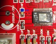
Ok, so front side of that 100k res, thanks Saturnus. What's a good local ground point to use?
View attachment 399378
I marked it in blue at the attached image.
Attachments
.JPG)
hi everybody!
ive just taken interest in building one of these little amps. infact i just tried to order the newest yj 2.0 boards (the blue ones) but the yuanjing site was down.
anyway i got a couple questions
i know the other boards can run on 12v dc. am i right in assuming this newer one will be able to run on 12v too? i know i wont get the full power. dont need it. still need it to sound its best of course!
also. can the new board still be bridged to make it a mono amp?
i figure the new boards shouldnt be all that different regarding these two things. please correct me if im wrong.
plus ive gathered from this thread that the board design is pretty much that of a member here. props to you sir! so i figured id ask my questions here.
thanks
phil
- Home
- Amplifiers
- Class D
- TPA3116D2 Amp