I was only speaking about the long cable to the speaker.
A common practice, at least to some of us.
Attachments
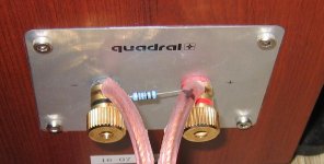
What is the value of the resistor?
It might be 68 ohms. It wouldn't be much lower, or it would be too charred to read the bands... 🙂
That's it. And it works. Resistance is close to cable HF wave impedance.
Pavel could you expound on this a bit more ..... ?
Pavel could you expound on this a bit more ..... ?
I can, pavel I hope you don't mind..
When the load "unloads", or goes above the cable's characteristic impedance, the cable will look like a capacitor to the amp. This resistor guarantees that no matter what the load does, the termination at that end will never be above the cable's impedance, so the amp will always see either inductance, or resistance.
For rf, it guarantees that there will not be cable resonances as a consequence of reflections.
The caveat is, if the cable is a low z type, that resistor would be too low a value, and it would consume power. When the cable is very low z, you'll have to put a cap in there as well to protect the resistor against lf power.
jn
What is the value of the resistor?
For that thickness insulation, I would guess around 120 to 150 ohms.
jn
Is there a simple way to determine the value of the resistor if you knew the impedance of the cable and the length of wire or is this a complex mathematical equation or do you have to have specific analysis equipment to determine the correct value? Would you also need to know the capacitance of the cable in question?
Ideally, the value of the resistor should be the same as the characteristic impedance of the cable.
I take it that the characteristic value of the cable is not the dc value of the resisitance? Otherwise I can't imagine using 150 ohms or thereabouts as JN has suggested a few posts back.
For that thickness insulation, I would guess around 120 to 150 ohms.
jn
What insulator thickness? How to relate that to the 168 Ohm used? Do you mean cable diameter?
The geometry of the speaker cable determines the characteristic impedance - a rule of thumb, the greater the distance between the centres of the two conducting paths the greater that impedance: think TV aerial wire, coax the usual values, the ribbon flex is 300R.
Way too many times I have heard "that does not matter" from those types.Incorrect.
Give them the right requirements, they will deliver.
jn
Yes, I agree, that's precisely my point - in audio, people can't specify the right requirements - hence, engineers don't have a clear, well-defined target ...
+1.
When I was working in the industry an example was a passive crossover component. Engineering had chosen as they normally do, by listening, specified as best they could on paper. Purchasing fond a cheaper source, met the specs but didn't sound as good.
Good reading is found here: Current-Driving of Loudspeakers by Esa Merilainen. yr 2010 340 pages.
"Eliminating Major Distortion and Interference Effects by the Physically Correct Operation Method".
Thx-RNMarsh
"Eliminating Major Distortion and Interference Effects by the Physically Correct Operation Method".
Thx-RNMarsh
Ya Mon !Ideally, the value of the resistor should be the same as the characteristic impedance of the cable.
As should be the output impedance of the source .....
But that's old school power transfer paradyme
I can, pavel I hope you don't mind..
When the load "unloads", or goes above the cable's characteristic impedance, the cable will look like a capacitor to the amp. This resistor guarantees that no matter what the load does, the termination at that end will never be above the cable's impedance, so the amp will always see either inductance, or resistance.
For rf, it guarantees that there will not be cable resonances as a consequence of reflections.
The caveat is, if the cable is a low z type, that resistor would be too low a value, and it would consume power. When the cable is very low z, you'll have to put a cap in there as well to protect the resistor against lf power.
jn
Hmm, we usually put such compensation in the xover , is this the same or different effect and is this why MIT cables have that little box ...🙂
PS: that resistor is color coded , why is everyone guessing its value......?
- Status
- Not open for further replies.
- Home
- Member Areas
- The Lounge
- John Curl's Blowtorch preamplifier part II