Perhaps I have been looking at this wrong, but it seemed the whole intent of this thread, "SKA GB150D now public domain... " was to explore builds "other than" with Greg's boards. If someone just wants to build the SKA using Greg's boards and parts, the very best thing to do would be to buy it all from him. That would be my suggestion.
Blessings, Terry
But if this is PD why should we keep Gregs boards outta it? Is there anything special with Gregs boards? Or with the communitys boards?
Regards
Member
Joined 2009
Paid Member
Hi Turbon,
Love your avatar!
Like most amplifiers, the stability and performance depends on the pcb layout. My first attempt had problems so I have made a new one - I hope to receive it soon. It's also in a different thread called 'TGM7'. I decided there was little to learn by building the amplifier on Greg's boards so I wanted to design my own and it has taught me a lot so far. So to answer your question, yes - it means there is always something special with the boards !
Last edited:
Hi Turbon,
Love your avatar!
Like most amplifiers, the stability and performance depends on the pcb layout. My first attempt had problems so I have made a new one - I hope to receive it soon. It's also in a different thread called 'TGM7'. I decided there was little to learn by building the amplifier on Greg's boards so I wanted to design my own and it has taught me a lot so far. So to answer your question, yes - it means there is always something special with the boards !
Thanks for the answer Bigun! Do you have links to yer competitors boards?
Regards
Member
Joined 2009
Paid Member
Greg's boards are here:
SKA sponsored Audio Forum - Products
Mine will be here, when they are ready:
http://www.diyaudio.com/forums/solid-state/239418-tgm7-amplifier-based-greg-ball-ska.html
fyi - I'm not offering boards in competition with Greg, but I'll make the design available (it's my design).
SKA sponsored Audio Forum - Products
Mine will be here, when they are ready:
http://www.diyaudio.com/forums/solid-state/239418-tgm7-amplifier-based-greg-ball-ska.html
fyi - I'm not offering boards in competition with Greg, but I'll make the design available (it's my design).
Greg's boards are here:
SKA sponsored Audio Forum - Products
Mine will be here, when they are ready:
http://www.diyaudio.com/forums/solid-state/239418-tgm7-amplifier-based-greg-ball-ska.html
fyi - I'm not offering boards in competition with Greg, but I'll make the design available (it's my design).
Thanks Bigun. Should you get a pair over - please PM me.
Regards
Well it's finally playing nice again. I guess the Phillips bc556B resistor that I have are just no good. Once I replaced them it stopped oscillating. The original problem must have been because I didn't have a ground loop breaker to the case because it is holding just fine now with the case all bolted together. I've had it playing for the last two hours. It doesn't sound quite as pleasing as it did before so I'm thinking it is probably that I dropped the bias down to 100mA. I think I had it set at 200mA before. The heatsinks are just barely warm right now so I think I can go up some in bias. I'll play with it some more tomorrow and report back.
Blessings, Terry
Blessings, Terry
The group of power wires comes in as a triplet to three close coupled terminals.
This minimises the radiated field.
The traces to feed the power devices are short. This minimises the radiated fields.
This is a layout/design feature I have advocated for a while.
Few seem to want to do it this way.
It makes me wonder why there is no loud shouting to remove the feature if it is so unpopular !
The group of power wires comes in as a triplet to three close coupled terminals.
This minimises the radiated field.
The traces to feed the power devices are short. This minimises the radiated fields.
This is a layout/design feature I have advocated for a while.
Few seem to want to do it this way.
It makes me wonder why there is no loud shouting to remove the feature if it is so unpopular !
That is the best way. But it is the pcb layout designer who must do the trick....
When we populate an existing pcb without having this feature then we can only twist the power wires to help....
The VSSA pcb from PMI has 3 closed terminals too so there are some DIY pcb available with that feature...
Fab
Pretty much all of the boards in the VSSA peeceebee thread have closely coupled power terminals. I have wondered about that with some of the other amps I have built, especially the Blameless amps. They all have wide spread rail inputs.
The group of power wires comes in as a triplet to three close coupled terminals.
This minimises the radiated field.
The traces to feed the power devices are short. This minimises the radiated fields.
This is a layout/design feature I have advocated for a while.
Few seem to want to do it this way.
It makes me wonder why there is no loud shouting to remove the feature if it is so unpopular !
I must say you are 100% right but the only reason I don't like it is when you try to remove the connectors, for example Fast-ons, it is really hard when all wires are all stuck to each others since you have no grip BUT in return it offers better immunity to radiated fields which is a big plus, whether it is audible is another story but it makes total sense.
It's just me being lazy... 😀
Ciao!
Do
Hi Guys,
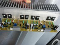
I got a chance to sit down this morning and do some close listening and I realized that on channel had way less bass and the highs had too much sizzle. This channel had one of the new boards I just assembled. The original board for that channel still had problems so I sat down with a DMM and went over it again and discovered that Q9 had gone short form E to B. I swapped it out and that fixed it so I swapped out the boards and now all is well. the amp is singing like big bird. I set the bias at 200mA and will let it play for while and see how the heatsinks feel.
So now, I need to fix the new boards. On the original boards, I didn't have any 330pf Micas for C2 so I used a ceramic. The new board has a Mica there. Then I used a 7pf Mica for C2 rather than the 6PF is calls for because that is all I had. The only other change is I used a WIMA .1uF for C8 and I used a big film cap in the originals. Anyway, I could use some advice as to what might be causing these boards to act the way they are. The scope looks like the attachment.
Thanks, Terry

Got both modules adjusted and tested. I played some music yesterday and it seems to be very good amplifier. I cannot tell the full story yet as I prefer giving it 10 hours at least. I'm also going through a bronco-pneumonia and have a hard time on concentration... I had initially planned listening a few albums but ended up falling asleep after 2-3 songs... But what I heard so far seems to be very good.
Ciao!
Do
Ciao!
Do
Hello Alex..... single layer PCB , first try .......😉
Regards Alex
can you tell me what PCB design and schematics software do you use ?
Thank you
Hi Guys,
I got my second pair of boards figured out. After checking the all the components again, I finally found the issue. I had installed a .47uf in C9 instead of 47uf. No wonder the sound was so pinched. All is well now and it is playing fine.
I got my second pair of boards figured out. After checking the all the components again, I finally found the issue. I had installed a .47uf in C9 instead of 47uf. No wonder the sound was so pinched. All is well now and it is playing fine.
Last edited:
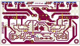
Where are the thermal sensing transistors?
The thermal sensing transistors are not placed on the heatsink yet, there will be required to drill 6mm holes for them. Other than that it is nice layout.
- Home
- Amplifiers
- Solid State
- SKA GB150D now public domain...