Whatever fold you end up with, room modes will make a mess of the frequency response anyway, EQ is your friend 😀.
The response of your cabinet will be quite different depending on it's proximity to boundaries and whether it is mouth up, mouth down, or laying on its side.
If you want to review the TH in multiples discussion a bit more it went from around post #1771 to #1781:
http://www.diyaudio.com/forums/subwoofers/119854-hornresp-179.html
Art, thanks for you comments and that link. Regarding room modes/EQ/placement, that is something I am still trying to get a handle on. I have a fair amount of experience tuning PA systems (31-Band, RTA), and I am very happy with my skills EQ'ing above 100 Hz or so, but 100 Hz and below I need to do some improvement on. If I try to auto-EQ with an RTA for those lower frequencies, it seems to sound worse than if I just leave it flat.
One of my sons has an iPhone app called AudioTools that is very impressive. He also has a miniature measurement mic that is built specifically for the iPhone. Using that in the RTA mode seems to see what is happening, and then adjust the EQ manually, seems to give us the best results. There still seems to strong/weak points of particular frequencies in certain rooms, so I am going to need to do some more research on that subject. Thanks.
email sent 🙂
THANK YOU Paul.
Paul (Silent Screamer) has done some behind the scenes coaching, helping me on one of the areas in SketchUp I couldn't figure out. He provided a very detailed response and even graphic examples. Thank you Paul for taking the time to do that, my frustration level has decreased dramatically.
And since you are following these posts, you must have some interest in Hornresp or tapped horn design theory. If you have any questions of you own, feel free to cut in and ask the Brainiac's for help. These guys have helped me immensely.
Question of the Day - Three Segment vs. Four Segment Tapped Horn
While I am getting my feet wet with a the three segment tapped horn, many of you more experienced designers are using the four segment style. I have also seen some comments urging Mr. McBean to allow even more segments to be modeled in Hornresp. My guess is that more segments allow for more creativity in trying to actually fold a horn into an actual box. Am I right or wrong on that?
Additionally, in a four segment tapped horn (S1-S5), how do you decide where to put the S3 measurement at? Do you do it more to make the Hornresp model look better, or is it to make the horn easier to fold into an actual cabinet (changing the angle of the horn expansion at that particular point)? Thanks.
Hi DHAA,
Placement of S3 in a 4-segment THs is explained here by soho54, Post #202: http://www.diyaudio.com/forums/subwoofers/175658-tham15-compact-15-tapped-horn-21.html
One of the reasons to use 4 over 3 segments is that it makes it possible to more closely approximate an overall exponential horn expansion in the model. Try exporting the horn data, and draw the horn from Post #167. It's pretty obvious, that one cannot be represented well in 3-segments. Using 4 segments will sometimes result in a horn w/ less internal volume, and higher efficiency (but not always).
There are also 2 different modes for the 4 segment TH:
- TH which uses two segments from S2 to S3 (driver front to back), and
- TH1 wich uses two segments from S3 to S5 (back of driver to mouth).
Just double click on the red TH (Hornresp Input screen), and you can switch the enclosure models.
Regards,
Hornresp does not consider the extra boundary the non-mouth frontal area of a cabinet presents.
In multiples that can be quite large with the type of cabinet you have designed, but would be only a fraction of the size if the mouth was the entire frontal size, as Hornresp considers it, another deviation between simulation and actual.
This sounds like you are talking about diffraction. None of the simple helmholtz simulators calculate diffraction and I seriously doubt most of the 1/4 wave simulators do it either, including Hornresp. MJK's software will do it in the more advanced second round of calculations but I believe he added it when he wanted to be able to simulate OB, which needs to know baffle size for obvious reasons. Akabak can probably do diffraction calculations as well, although I've never bothered to try.
This is actually really simple - if the program lets you input the baffle dimensions, it's probably using them to calculate diffraction. If there is no baffle dimension inputs, there's no possible way it can address diffraction. I don't think there's any program that's going to attempt to calculate diffraction based on the size of the mouth alone.
Using a flat expansion in the last horn section of Hornresp to approximate the frontal area does not conform to measured reality.
I have no idea what this means. But there's nothing you can do inside Hornresp to approximate diffraction.
If you want to know the "fine details", you still have to make sawdust and measure results.
Art
If you want to know the fine details you can make sawdust and measure or you can simply simulate the diffraction. I have three different programs on my computer right now that can do it.
Most people don't need to bother with it at all since most people build tiny little subs that don't play very high in frequency, so the sub's entire response will be in the flat full loss part of the diffraction curve below the baffle step. But for people that make large subs, especially if they will be stacking the subs, and especially if the subs need to play high in frequency, it can be worth the trouble to simulate diffraction since the passband could extend all the way up into the baffle step region and skew the response curve.
Hi just a guy,
Post #186: ""Quote: Using a flat expansion in the last horn section of Hornresp to approximate the frontal area does not conform to measured reality."
I have no idea what this means. But there's nothing you can do inside Hornresp to approximate diffraction."
I think Art is talking about TH1 w/ the S3/S4 section establishing the mouth, and a very short L45 / a larger S5 establishing the baffle.
That indeed does something, but I have no measurement capability, or setup facility, to evaluate it through measurements. Just tried it quickly on the one from Post #47, go TH1, set S5 to 20000, L45 to .1cm, calculate, and compare to the original.
Regards,
Last edited:
Originally Posted by weltersys
Hornresp does not consider the extra boundary the non-mouth frontal area of a cabinet presents.
In multiples that can be quite large with the type of cabinet you have designed, but would be only a fraction of the size if the mouth was the entire frontal size, as Hornresp considers it, another deviation between simulation and actual.
Cabinets with large frontal areas or "barn doors" along side create a boundary, the boundary increases forward directivity in the same fashion as going from full space to half space to 1/4 to 1/8 space.
Relatively small "barn doors" (for instance, doubling the frontal area of the Keystone TH and other FLH) can increase the on axis level by an average of 3 dB down to Fc.
One can approximate the boundary in Hornresp by having the last horn segment expand rapidly (a "flat" expansion), that is, use S3 as the mouth exit area, then enter the minimum L3/L4 distance, then enter S4 as the cabinet's frontal area.
Having done that, one finds that the measured results do not conform to the sim.
Art
Hornresp does not consider the extra boundary the non-mouth frontal area of a cabinet presents.
In multiples that can be quite large with the type of cabinet you have designed, but would be only a fraction of the size if the mouth was the entire frontal size, as Hornresp considers it, another deviation between simulation and actual.
The lower wavelengths a sub produces are long enough to diffract around any typical size enclosure, but the upper frequencies are affected (controlled) by the baffle dimensions and the horn itself to some extent.This sounds like you are talking about diffraction.
Quote:
Using a flat expansion in the last horn section of Hornresp to approximate the frontal area does not conform to measured reality.
I have no idea what this means. But there's nothing you can do inside Hornresp to approximate diffraction.
Cabinets with large frontal areas or "barn doors" along side create a boundary, the boundary increases forward directivity in the same fashion as going from full space to half space to 1/4 to 1/8 space.
Relatively small "barn doors" (for instance, doubling the frontal area of the Keystone TH and other FLH) can increase the on axis level by an average of 3 dB down to Fc.
One can approximate the boundary in Hornresp by having the last horn segment expand rapidly (a "flat" expansion), that is, use S3 as the mouth exit area, then enter the minimum L3/L4 distance, then enter S4 as the cabinet's frontal area.
Having done that, one finds that the measured results do not conform to the sim.
Art
Hi DHAA,
Placement of S3 in a 4-segment THs is explained here by soho54, Post #202: http://www.diyaudio.com/forums/subwoofers/175658-tham15-compact-15-tapped-horn-21.html
Thanks again Oliver for that link, there's some great information going on there. It was actually either the THAM 10 or THAM12 that I heard about on another website, and what got me interested in tapped horns. I had started reading that THAM15 series of posts a while back, but never finished it - it was getting too deep for my understanding at that point. But I just started reading from post #202 backwards, and there is some very helpful info being exchanged there. Here is a post of yours (#201) from three years ago that seems to some up my confusion pretty well:
I think I got it now, it's the difference between designing a fold from a model, and iterratively changing both until they meet, and deriving a model from an already existing fold, where the fold cannot be changed. Naturally, now I'll have a lot of stuff to look at again.
I didn't make any progress on laying out my fold last night as I had some other things I had been neglecting that had to be done. I will try to make some progress tonight.
HR for a rear-loaded vented box - but how ?
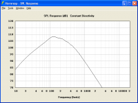
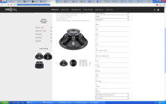
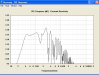
Hi to all, this informative thread is funny ! So I ask a parallel question regarding a horn for my 4 BC 18PS76 ( wanted to use them for an open baffle), but I prefer to build a horn-speaker with them. Specs -> first attachment. A TH results in an enormous box, 55 x 55 x 240 cm... As a frontloaded bass-horn the response is not bad ( 2. image). But the thing that rings in my head is a horn-loaded vented box - I don't know what it is exactly and how to simulate it. Carl Huff has built a wonderful enclosure ( Richard Long's Waldorf restoration with 2 JBL2240, great). And Thawach makes these front-loaded enclosures. The gotohorn2 sideboard design is simply out of my reach. BCspeakers has a finished plan on their site : S18H. The 220 cm path and the small mouth don't seem to sound good in HR ragged response and low SPL, so I prefer to mount the driver to the baffle ( looks much cooler than hidden...) and use the box as a rear-loaded horn. Question : do you sim a frontloaded horn and think for yourself : this is a rear-loaded one ? I can almost recite the fine HR manual but am not shure. Any comment is wellcome. Thanks !
Hi to all, this informative thread is funny ! So I ask a parallel question regarding a horn for my 4 BC 18PS76 ( wanted to use them for an open baffle), but I prefer to build a horn-speaker with them. Specs -> first attachment. A TH results in an enormous box, 55 x 55 x 240 cm... As a frontloaded bass-horn the response is not bad ( 2. image). But the thing that rings in my head is a horn-loaded vented box - I don't know what it is exactly and how to simulate it. Carl Huff has built a wonderful enclosure ( Richard Long's Waldorf restoration with 2 JBL2240, great). And Thawach makes these front-loaded enclosures. The gotohorn2 sideboard design is simply out of my reach. BCspeakers has a finished plan on their site : S18H. The 220 cm path and the small mouth don't seem to sound good in HR ragged response and low SPL, so I prefer to mount the driver to the baffle ( looks much cooler than hidden...) and use the box as a rear-loaded horn. Question : do you sim a frontloaded horn and think for yourself : this is a rear-loaded one ? I can almost recite the fine HR manual but am not shure. Any comment is wellcome. Thanks !
Attachments
A front loaded horn with bass reflex can be simulated using the compound horn function.Question : do you sim a frontloaded horn and think for yourself : this is a rear-loaded one ?
Hornresp for Dum... hmm... Everyone 😉 - Page 2 - Home Theater Forum and Systems - HomeTheaterShack.com
I ask a parallel question regarding a horn for my 4 BC 18PS76.
Chano, First things first, are you an Old Man, or a Young Hooligan?
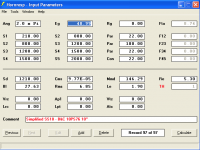
Can I sell you a tapped horn which is only approximately 50 x 50 x 120cm, will do about 125 dB with 300 watts RMS, has fairly flat response to 40Hz, and is super easy to build?
(Don't get too excited Brainiac's, I didn't design this myself. It is JBell's prototype - The Simplified SS18).
Here it is modeled with the B&C 18PS76 driver.
Attachments
Last edited:
49 volts is more like 450 watts in to 5.3 ohm (minima), what is the excursion at 125 dB?Can I sell you a tapped horn which is only approximately 50 x 50 x 120cm, will do about 125 dB with 300 watts RMS, has fairly flat response to 40Hz, and is super easy to build?
Question of the Night - How to properly calculate Max SPL @ Xmax
Art, you have pretty good eye sight for an old man. If you are working the night shift this evening, I am going to throw that question back at you.
How to properly calculate Max SPL @ Xmax?
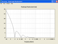
Here is what I did. On the HR input screen, I double clicked on the "e.g." box. On the pop-up, I entered '300 watts' and '8 ohms'(nominal impedance). It calculated 48.99 volts. I then went to the "Diaphragm Displacement" window and it was peaking at approximately '7,' so there was my answer.
After your comment, I tried it with '450 watts' and '5.3 ohms' (impedance minima) and it calculated 48.84 volts. I then checked the SPL curve, and the Diaphragm Displacement, and they were basically identical to my previous results.
So, How to properly calculate Max SPL @ Xmax?
For a bonus question, when you have a SPL graph up in HR, under "Tools" is a choice for "Maximum SPL." When I check that, I enter '300 watts' and '7mm.' The SPL graph changes, and both of the bottom curves come down to approximately 125 dB. Is that the proper way to check Max SPL?
Attached is a HR data export if you want to check my comments. Thanks.
49 volts is more like 450 watts in to 5.3 ohm (minima), what is the excursion at 125 dB?
Art, you have pretty good eye sight for an old man. If you are working the night shift this evening, I am going to throw that question back at you.
How to properly calculate Max SPL @ Xmax?
Here is what I did. On the HR input screen, I double clicked on the "e.g." box. On the pop-up, I entered '300 watts' and '8 ohms'(nominal impedance). It calculated 48.99 volts. I then went to the "Diaphragm Displacement" window and it was peaking at approximately '7,' so there was my answer.
After your comment, I tried it with '450 watts' and '5.3 ohms' (impedance minima) and it calculated 48.84 volts. I then checked the SPL curve, and the Diaphragm Displacement, and they were basically identical to my previous results.
So, How to properly calculate Max SPL @ Xmax?
For a bonus question, when you have a SPL graph up in HR, under "Tools" is a choice for "Maximum SPL." When I check that, I enter '300 watts' and '7mm.' The SPL graph changes, and both of the bottom curves come down to approximately 125 dB. Is that the proper way to check Max SPL?
Attached is a HR data export if you want to check my comments. Thanks.
Attachments
forget thinking about watts for a moment.
we speak in volts generally. now, assuming you know xmax of the driver. input a voltage (say, 50 for that design), then calculate spl. Open up the "filter wizard. change the filter to bandpass. plop a hipass on there (18 db/oct is a good one for tapped horns, because excursion maxima usually hapens within the passband, and the 18db per oct helps bring that peak down a bit). adjust the hipass frequency untill the horn does not exceed xmax at any frequency (and you dont sacrifice too much spl). you can check the "show baseline" box to verify this.
we speak in volts generally. now, assuming you know xmax of the driver. input a voltage (say, 50 for that design), then calculate spl. Open up the "filter wizard. change the filter to bandpass. plop a hipass on there (18 db/oct is a good one for tapped horns, because excursion maxima usually hapens within the passband, and the 18db per oct helps bring that peak down a bit). adjust the hipass frequency untill the horn does not exceed xmax at any frequency (and you dont sacrifice too much spl). you can check the "show baseline" box to verify this.
I think Art is talking about TH1 w/ the S3/S4 section establishing the mouth, and a very short L45 / a larger S5 establishing the baffle.
That indeed does something, but I have no measurement capability, or setup facility, to evaluate it through measurements. Just tried it quickly on the one from Post #47, go TH1, set S5 to 20000, L45 to .1cm, calculate, and compare to the original.
Regards,
I agree, this indeed does something. Obviously you guys have discussed this before. I wasn't aware of this and it's interesting. Got links?
Originally Posted by weltersys
The lower wavelengths a sub produces are long enough to diffract around any typical size enclosure, but the upper frequencies are affected (controlled) by the baffle dimensions...
Agreed, and this is what diffraction usually looks like for a baffle that's 17 x 48 inches with a sound source near the bottom.
An externally hosted image should be here but it was not working when we last tested it.
And now double wide.
An externally hosted image should be here but it was not working when we last tested it.
Le, which can't be properly simulated in Hornresp might counteract some or all of the rising response above 40 or 50 hz, leaving very little actual gain in a subwoofer's bandwidth.
... but the upper frequencies are affected (controlled) by the baffle dimensions and the horn itself to some extent...
... One can approximate the boundary in Hornresp by having the last horn segment expand rapidly (a "flat" expansion), that is, use S3 as the mouth exit area, then enter the minimum L3/L4 distance, then enter S4 as the cabinet's frontal area.
I don't think that's a good way to approximate the baffle effect. I'm not sure why the graph changes so much when you do the "flat expansion" thing, and I'm not sure that this is a valid way to approximate a baffle.
Cabinets with large frontal areas or "barn doors" along side create a boundary, the boundary increases forward directivity in the same fashion as going from full space to half space to 1/4 to 1/8 space.
The boundary that's created by a stack is a wall (a flat single surface). If that wall gets big enough, that wall in conjunction with the existing 2 pi ground measurement will effectively be the same as a 1 pi simulation. This is directly due to diffraction and the baffle step frequency, you could gain as much as 6 db in forward directivity if the wall gets as big as the wavelength.
The problem here is that even with two subs (17 x 48 inch baffles) it isn't nearly large enough to provide 3 db of gain with a second cab (compared to a single cab) all the way down to fc. So if you are getting 3 db of gain on top of what the Hornresp multiple speakers tool is suggesting just by adding a second cab I'd be interested in reading about that if you have links.
Last edited:
The measured gain from two small cabinets is generally only 6 dB over one cabinet.I agree, this indeed does something. Obviously you guys have discussed this before. I wasn't aware of this and it's interesting. Got links?
The boundary that's created by a stack is a wall (a flat single surface).
The problem here is that even with two subs (17 x 48 inch baffles) it isn't nearly large enough to provide 3 db of gain with a second cab (compared to a single cab) all the way down to fc. So if you are getting 3 db of gain on top of what the Hornresp multiple speakers tool is suggesting just by adding a second cab I'd be interested in reading about that if you have links.
The extra 3 dB I mentioned was doubling the frontal area of a larger area than 17 x 48.
Here are some links to posts exploring the effect of boundary enhancement (AKA "Barn Doors" or "Horn Extenders)
http://www.diyaudio.com/forums/subwoofers/184986-horn-extender-wave-guide-th.html
http://www.diyaudio.com/forums/subwoofers/204472-multiple-cabinet-combined-response.html
The additional gain relatively small "barn doors" can impart to any type of cabinet to the LF cutoff was a surprise to me.
Art
Art
THANK YOU Paul.
Paul (Silent Screamer) has done some behind the scenes coaching, helping me on one of the areas in SketchUp I couldn't figure out. He provided a very detailed response and even graphic examples. Thank you Paul for taking the time to do that, my frustration level has decreased dramatically.
And since you are following these posts, you must have some interest in Hornresp or tapped horn design theory. If you have any questions of you own, feel free to cut in and ask the Brainiac's for help. These guys have helped me immensely.
You're most welcome, and should you require further help just email me on that same email address I sent you.
There are a few little tricks I discovered quite by accident, and some by just nutting it out i.e. when using the protractor you don't have to try get the angle you want by moving it to the exact angle you can use the / and backspace once and just type in the angle you want (spent ages doing it the hard way).
As for HR yes I was keen to learn how to use it but unfortunately the help section is close to useless to visual people like me (even with the other dummies websites). I need to visually see and understand the what / why before I can make sense of things. I thought I was close a couple of times to understanding it but it never quite latched for me so I have pretty much given up on it and I am building my current sub with a TC Sounds Pro 5400 and two 18" passive radiators.
Last edited:
forget thinking about watts for a moment.
we speak in volts generally. now, assuming you know xmax of the driver. input a voltage (say, 50 for that design), then calculate spl. Open up the "filter wizard. change the filter to bandpass. plop a hipass on there (18 db/oct is a good one for tapped horns, because excursion maxima usually hapens within the passband, and the 18db per oct helps bring that peak down a bit). adjust the hipass frequency untill the horn does not exceed xmax at any frequency (and you dont sacrifice too much spl). you can check the "show baseline" box to verify this.
Well, Sine143, I am glad someone is working the night shift this evening.
Thanks for taking the time to explain that to me, that is yet another thing I wasn't doing right.
I played around with the information you gave me, and this was what to me seemed like a fair compromise.
- 55 volts with a 3rd order (-18dB) Butterworth filter set at 40Hz.
If you are having a slow night, would you mind downloading the HR Data Export from post #194 and seeing if what I came up with is a reasonable compromise. It looks like Art has gone to bed already.
There are a few little tricks I discovered quite by accident .. . . you don't have to try get the angle you want by moving it to the exact angle you can use the / and just type in the angle you want (spent ages doing it the hard way).
Once I realized how the "Measurements" box worked, it has really made things a lot easier. I was trying to stretch things perfectly and was getting very frustrated.
I have been punching holes in things per your instructions all day today, I am glad I finally understand that process. Thanks again. Do you use SketchUp professionally at all, or just as a hobby?
As for HR yes I was keen to learn how to use it but unfortunately the help section is close to useless to visual people like me (even with the other dummies websites). I need to visually see and understand the what / why before I can make sense of things. I thought I was close a couple of times to understanding it but it never quite latched for me so I have pretty much given up on it and I am building my current sub with a TC Sounds Pro 5400 and two 18" passive radiators.
Hey, did you Brainiac's here that? Anyone interested in making a youtube type screen capture video for the common men like Paul and myself?
- Status
- Not open for further replies.
- Home
- Loudspeakers
- Subwoofers
- Hornresp Brainiacs - Help an Old Man