SketchUp Basics for Newbies and Old Men
I made some good progress leaning SketchUp today. It really isn't that much different that a lot of other graphics programs, except for two key concepts. Unfortunately, these two concepts took me a while to fully comprehend, so if anyone else is interested in learning SketchUp, concentrate on learning these two commands first and it will save you a lot of grief:
Components: This take a group of lines and allow you to move them as a group. I didn't realize this for a while, so when I tried to move a rectangle, it would it would distort into a trapezoid, or whatever. For speaker cabinet designs, you need to make each separate piece of plywood a different component. SketchUp has a special process to select and label something as a component - then they can be moved around easily
Move: Moving an object in SketchUp is very different than any other graphics program (or any other computer application) I have seen. If you want to corners to line up perfectly you can not just drag it over. You click on the edge of what you want to move, then move your mouse (not drag it) to the edge you want to mate it up to. Then click you mouse, and it snaps over and lines up perfectly.
If you learn to do these two things first, I really don't think it is that difficult of a program to use, especially if you are just using it for 2D work.
Silent Screamer, I am still having a few problems I could use some help on though. I need to find a way to clearly describe what my problems are (or find a way to illustrate them), so I will probably be asking for you advice if I can properly explain what I need.
Hi DHAA,
Just PM me an email address and we can swap .skp files and discuss offline since we are in different time zones.
Just PM me an email address and we can swap .skp files and discuss offline since we are in different time zones.
Oliver, the attachment you included with post #152 was excellent. Just seeing those images really cleared up some things for me, I really appreciate you taking the time to do that for me.
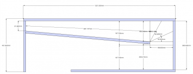
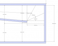
I didn't get much time to work on my horn wrap today, but I have included two attachment to show you what I have done so far. It is not correct right now, but at least I think I am starting to understand the horn wrapping concept. I followed you HR Horn Date Export instructions PROPERLY finally, and that is looking good.
So if I understand you previous comments correctly, this is what I need to do:
- If I am trying to fit this particular horn in a particular size cabinet, I try to get it as close as I can by adjusting the baffle board.
- If it doesn't quite fit properly, I go back to HR and try to make some changes that would help it fit. Then I export the horn data again and try laying it out to see if it will fit.
- If after a few tries it still isn't fitting perfectly, then it is probably time to change the dimension of the cabinet to make it an easier fit.
Is that the right idea? For me, this horn wrapping is a lot more difficult that I thought it would be. But I seem to have a better understanding of SketchUp now, so maybe that will not longer be a hinderance and things will go a little smoother.
Oliver, Would you be willing to do a HR data export for that design. It would help me even more if I could see that also.
I didn't get much time to work on my horn wrap today, but I have included two attachment to show you what I have done so far. It is not correct right now, but at least I think I am starting to understand the horn wrapping concept. I followed you HR Horn Date Export instructions PROPERLY finally, and that is looking good.
So if I understand you previous comments correctly, this is what I need to do:
- If I am trying to fit this particular horn in a particular size cabinet, I try to get it as close as I can by adjusting the baffle board.
- If it doesn't quite fit properly, I go back to HR and try to make some changes that would help it fit. Then I export the horn data again and try laying it out to see if it will fit.
- If after a few tries it still isn't fitting perfectly, then it is probably time to change the dimension of the cabinet to make it an easier fit.
Is that the right idea? For me, this horn wrapping is a lot more difficult that I thought it would be. But I seem to have a better understanding of SketchUp now, so maybe that will not longer be a hinderance and things will go a little smoother.
If you want more output you'll have to go w/ a bigger box, e.g.: I did a quick 4 segments Hornresp w/ 4:1 compression ratio, a much bigger mouth, and about V_net=240L, and that really bumps the efficiency and the SPL up.
Oliver, Would you be willing to do a HR data export for that design. It would help me even more if I could see that also.
Attachments
Just PM me an email address and we can swap .skp files and discuss offline since we are in different time zones.
Wow, thank you Sir! I will try to get something together for you tomorrow.
There are some amazing people on the forum!
From your diagram it looks like you're taking sections using lines that are perpendicular to the outside walls. For better accuracy, I think those section lines need to be (90-(A1+A2)) degrees to the internal panel. So for example if that internal panel is at 5 degrees and the adjacent external panel is at 0 degrees, the section line should be (90-(5+0)) = 85 degrees. I think this gives a slightly more accurate indication of both path length to the section and cross-sectional area at the section. It does make the calculations a bit more complex however.
...which is why I use an Excel spreadsheet to do them for me 🙂
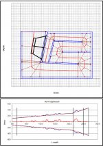
I've attached how I map out the path length in my spreadsheet as an example.
...which is why I use an Excel spreadsheet to do them for me 🙂
I've attached how I map out the path length in my spreadsheet as an example.
Attachments
From your diagram it looks like you're taking sections using lines that are perpendicular to the outside walls. For better accuracy, I think those section lines need to be (90-(A1+A2)) degrees to the internal panel. So for example if that internal panel is at 5 degrees and the adjacent external panel is at 0 degrees, the section line should be (90-(5+0)) = 85 degrees. I think this gives a slightly more accurate indication of both path length to the section and cross-sectional area at the section. It does make the calculations a bit more complex however.
...which is why I use an Excel spreadsheet to do them for me 🙂 I've attached how I map out the path length in my spreadsheet as an example.
Mr. Steele, that is very interesting. Is this an example of what you are talking about - post #109: http://www.diyaudio.com/forums/subwoofers/171747-spreadsheet-folded-horn-layouts-11.html#post3758901
"It does make the calculations a bit more complex however."
I am starting to think you guys are into sadomasochism. My head is starting to throb. Seriously though, I will have to take a closer look at this tomorrow. I had already downloaded the file you posted in post #109 of the Spreadsheet forum and it really looks interesting - but I just haven't had time to try to apply it yet. I am having enough problems with the method Oliver (tb46) has suggested, so I better at least get that right first before getting in even deeper. Thanks.
Last edited:
Post #163
Post #163
Hi DHAA,
You are making good progress. I have not done the number on the particular 180 degree bend, but what you have there looks much better than before. One quick check I use every now and then is to subtract the duct heights before/middle/after around the bend to see if there is a reasonable looking progression. It helps to do a few of these.
A quick note on going from Hornresp to the drawing: for simulations that have only Par segments it is not necessary to export the whole horn data every time. Just make a spreadsheet as I showed earlier to calculate the duct heights from the areas, then plot a line w/ S1's duct height, from the middle of that line draw L12 orthagonally, @ the end of the line draw the S2 duct height (w/ it's middle @ the end of the L12 line) orthagonally, and so on. Then, when you connect the duct height line ends, you have your horn expansion lines w/ the length lines as the center axis. (This kind of stuff gets so wordy....)
No problem to share the Hornresp data for a "bigger box", just keep in mind that the Thiel/Small parameters may well be "subject to change without notice", and there goes all that fine work. So, when you get to the point of doing this for real, measure the dang parameters first (or go w/ a known good source). 🙂 This might be a hard one to fold, or, maybe a good one to try out Brian's spreadsheet using the SS15 type layout he posted in #165, that's very nice work.
Regards,
Attachments
Last edited:
From your diagram it looks like you're taking sections using lines that are perpendicular to the outside walls. For better accuracy, I think those section lines need to be (90-(A1+A2)) degrees to the internal panel. So for example if that internal panel is at 5 degrees and the adjacent external panel is at 0 degrees, the section line should be (90-(5+0)) = 85 degrees.
My mistake - the calculation should actually be (90-((A1+A2)/2)). So, given the example above, the section line should be at 87.5 degrees. For small angles, the difference should be minor compared to what you're doing now.
I am starting to think you guys are into sadomasochism.
LOL, it did take about a month and lots of tearing of hair out to get the "SS15" spreadsheet to where it is today 🙂. The nice thing now though is that it allows me to tweak the layout to match different drivers and output requirements.
This might be a hard one to fold, or, maybe a good one to try out Brian's spreadsheet using the SS15 type layout he posted in #165, that's very nice work.
I tried it already. I think S1 for this particular design is too small for it to work in an SS15 type layout. There doesn't seem to be any way to wrap the fold in the top part of the box in a way that leaves the expansion uniform between the S1 and S3 points, which it will need to be for this type of layout.
Post #170
Hi Brian,
I was afraid of that. For what it's worth the S1 dimension is not critical. Just S2 is fixed by the choice of a 4:1 compression ratio. I have not spend any time on trying to fold this one, but I had a hunch it might not be easy, even the S4/S5 area may be a problem.
Regards,
Hi Brian,
I was afraid of that. For what it's worth the S1 dimension is not critical. Just S2 is fixed by the choice of a 4:1 compression ratio. I have not spend any time on trying to fold this one, but I had a hunch it might not be easy, even the S4/S5 area may be a problem.
Regards,
Question of the Day - Low Frequency Extension of Multiple Tapped Horns
O.K. Brainiac’s, while I am still stumbling through stuffing my horn into my box, here is something for you to discuss, if you are so inclined.
I believe I read somewhere, when I first started investigation tapped horns, that MULTIPLE TAPPED HORN’S DO NOT OFFER LOW FREQUENCY EXTENSION. They are similar to a ported or sealed subwoofer, whereas multiple cabs provide more SPL - but DO NOT change in overall frequency response compared to a single cab.
But what I find interesting is that when using Hornresp’s “Multiple Speakers” function, LOW FREQUENCY EXTENSION DOES OCCUR WITH MULTIPLE CABINETS!!!!!
So, what is the definitive answer to this question?
Hornresp differs from actual measured response slightly.But what I find interesting is that when using Hornresp’s “Multiple Speakers” function, LOW FREQUENCY EXTENSION DOES OCCUR WITH MULTIPLE CABINETS!!!!!
So, what is the definitive answer to this question?
No big deal, but anyone building TH counting on getting a lower corner in multiples will be sad to hear it does not occur.
There are no measured results indicating any lower corner with multiple TH.
That said, multiple cabinets will smooth out response, and doubling cabinets (and power) results in a six dB increase, which is quite a bit.
The lower in frequency response the more apparent the difference is, at 1000 Hz it takes a 10 dB increase to sound twice as loud, while at 20 Hz it only takes 5 dB to sound twice as loud.
There also is no reason getting hung up about a few inches difference in path length- if you have decided on a 48" tall box with a single bend the path length (and Fb) is what it is, the only change in path length possible depends on where the exit is, and that difference is slight, probably less than the difference of one musical note interval.
Art
... MULTIPLE TAPPED HORN’S DO NOT OFFER LOW FREQUENCY EXTENSION.

That measurement says it was done by Ian Beaver, who works at Danley Sound Labs. So if this actually came from DSL I'd imagine it's about as definitive as we are going to get.
Personally I've never really worried about this issue. People usually use tapped horns if they want to use a single cab or front loaded horns if they want to use a stack. (That's been my impression at least, and what I would do.) Front loaded horns provide SIGNIFICANT improvements in multiples.
Anyway, use the multiple speakers tool for ported boxes and you will see the tuning drop a bit as well, it's not just horns that exhibit this behavior in Hornresp.
EDIT - Cool, weltersys and I posted at exactly the same time, I've never had that happen before.
That measurement says it was done by Ian Beaver, who works at Danley Sound Labs. So if this actually came from DSL I'd imagine it's about as definitive as we are going to get.
That looks pretty definitive to me. Those results suggest that the corner frequency is being pushed downwards as the number of TH cabinets goes up - as predicted by HornResp.
Front loaded horns provide SIGNIFICANT improvements in multiples.
Just a quick note on this part. Even a stack of 8 front loaded horns will only extend the response a couple hz lower, but the low frequency response gets a lot stronger when stacked. If you don't know what I'm talking about I can post a picture later.
My position is simple . .
Did I read that right, SIMPLE? That is the first time anyone on the series of posts has used that term. I like it, let's us it more often!
Thanks Oliver for all the help you have given me ideas on how to correctly fold a horn. I don't think I properly understood your suggestion to use the spreadsheet. Tonight I will start over, re-read all your posts on the subject, and try again. I will probably be asking you to clarify a few points, as either I am over-thinking it, or just going senile.
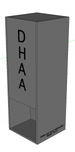
On the positive side of things, I just banged out a 3D version of the TSF15 on my lunch hour, and at least I am starting to understand that process.
There also is no reason getting hung up about a few inches difference in path length- if you have decided on a 48" tall box with a single bend the path length (and Fb) is what it is, the only change in path length possible depends on where the exit is, and that difference is slight, probably less than the difference of one musical note interval.
Thanks for the comment, Art. That puts thing in a clearer perspective for me. I get obsessed with details sometimes, but somehow I will make this fold happen.
Even a stack of 8 front loaded horns will only extend the response a couple hz lower, but the low frequency response gets a lot stronger when stacked. If you don't know what I'm talking about I can post a picture later.
Thanks just a guy, I believe I know what you mean by that comment.
Attachments
That looks pretty definitive to me. Those results suggest that the corner frequency is being pushed downwards as the number of TH cabinets goes up - as predicted by HornResp.
Ironically, the first time I saw this picture it was posted by someone using it to argue exactly the opposite of what you just said. I suppose there's a bit of room for interpretation here.
(I wouldn't try to take this picture too literally, we don't know the measurement conditions, where the mic was placed, how the cabs were stacked, etc. All I suggest taking away from this is that if there is a change in the LF corner at all it isn't a big change.)
Whatever fold you end up with, room modes will make a mess of the frequency response anyway, EQ is your friend 😀.Thanks for the comment, Art. That puts thing in a clearer perspective for me. I get obsessed with details sometimes, but somehow I will make this fold happen.
The response of your cabinet will be quite different depending on it's proximity to boundaries and whether it is mouth up, mouth down, or laying on its side.
If you want to review the TH in multiples discussion a bit more it went from around post #1771 to #1781:
http://www.diyaudio.com/forums/subwoofers/119854-hornresp-179.html
Hornresp does not consider the extra boundary the non-mouth frontal area of a cabinet presents.
In multiples that can be quite large with the type of cabinet you have designed, but would be only a fraction of the size if the mouth was the entire frontal size, as Hornresp considers it, another deviation between simulation and actual.
Using a flat expansion in the last horn section of Hornresp to approximate the frontal area does not conform to measured reality.
If you want to know the "fine details", you still have to make sawdust and measure results
 .
.Art
- Status
- Not open for further replies.
- Home
- Loudspeakers
- Subwoofers
- Hornresp Brainiacs - Help an Old Man