So GM and Just a Guy, who is more senile, myself or Walter and Oliver?
Just so you know, medical diagnosis is not my area of expertise, although I suspect we are all a bit nutty in our own ways.
As far as the Keystone goes, unfortunately I am in no position to comment. There is so much info on this design I'm not sure if I've ever seen the final plans, the official response measurements, and I know I've never simulated it. (EDIT - I actually did sim it once but I used someone else's Hornresp inputs and was told they were not accurate.)
In the past Weltersys and I have disagreed on the accuracy of simulations and I've heard this cab can't be accurately simulated. Despite the simplifying assumptions of the simulators I find it hard to believe that you can't get really really close regardless of the shape of the mouth.
If someone wants to PM me the official plans and measurements I'll sim this design but it won't be anytime soon. Holiday festivities are still in full swing here with geographically distant relatives taking up time and space and I'm getting way behind in my seasonal work, so I'm busy for quite awhile.
I do agree though, this design is probably not the one you want to start with to learn Hornresp.
Last edited:
Exhibit A - Grandpa's Booty Shaker (GBS15)
O.K., here it is - The GBS15 (aka Grandpa's Booty Shaker). I have created quite a few experiments in HR, but this is one that that would be simple to transfer from HR into an actual build. I used the simplest tapped horn form to create this:
https://www.dropbox.com/s/12l8esyongqrh1w/Simple Tapped Horn Example.png
For a driver I used the new Dayton Audio PA385S-8 15" Pro Subwoofer. It looks like parts-express.com will start selling next week:
Dayton Audio PA385S-8 15" Pro Subwoofer 4" VC 8 Ohm | 295-040
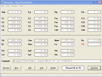
My goals in this design were to keep it as small as possible and to weigh less than I do. It needs to fit easily on a refrigerator dolly. This would be used for a rock band PA sub, so I don't need the low-end extension the hip-hoppers do, solid from around 45Hz to 100Hz would make me happy. Here is my HR input screen:
https://www.dropbox.com/s/fjp370nohlqs66g/GBS15 HR Input.png
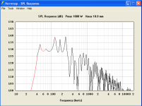
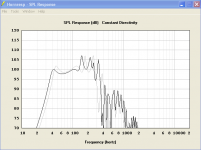
Using the simple fold mentioned above, it looks like this horn would end up being approximately 17" x 17' x 48". Here is the frequency response:
https://www.dropbox.com/s/8skn0voocbzdvpt/GBS15 - SPL.png
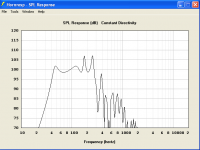
Here is the Max SPL with 1000 watts and Xmax 10:
https://www.dropbox.com/s/7c9heun30wvqqkg/GBS15 - Max. SPL.png
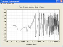
Here is the phase response:
https://www.dropbox.com/s/aep375t7m03r1le/GBS15 - Phase.png
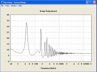
I am not totally up to speed on exactly how horn paths modify acoustic impedance or group delay. Here are the graphs for that info if anyone would like to comment:
https://www.dropbox.com/s/oqi2llb8p0zw2ra/GBS15 - Ac. Imp..png
https://www.dropbox.com/s/is4dc3q5fgaa4kp/GBS15 - Group Delay.png
I am not sure I am going to actually try to build this, but I would appreciate comments of the plus's and minus's of this design. Remember, I like criticism - it is the only way I will learn. I would love to hear any way I can make improvements. And if this design is a pile of shite, please let me know and I will start over again. Thanks.
O.K., here it is - The GBS15 (aka Grandpa's Booty Shaker). I have created quite a few experiments in HR, but this is one that that would be simple to transfer from HR into an actual build. I used the simplest tapped horn form to create this:
https://www.dropbox.com/s/12l8esyongqrh1w/Simple Tapped Horn Example.png
For a driver I used the new Dayton Audio PA385S-8 15" Pro Subwoofer. It looks like parts-express.com will start selling next week:
Dayton Audio PA385S-8 15" Pro Subwoofer 4" VC 8 Ohm | 295-040
My goals in this design were to keep it as small as possible and to weigh less than I do. It needs to fit easily on a refrigerator dolly. This would be used for a rock band PA sub, so I don't need the low-end extension the hip-hoppers do, solid from around 45Hz to 100Hz would make me happy. Here is my HR input screen:
https://www.dropbox.com/s/fjp370nohlqs66g/GBS15 HR Input.png
Using the simple fold mentioned above, it looks like this horn would end up being approximately 17" x 17' x 48". Here is the frequency response:
https://www.dropbox.com/s/8skn0voocbzdvpt/GBS15 - SPL.png
Here is the Max SPL with 1000 watts and Xmax 10:
https://www.dropbox.com/s/7c9heun30wvqqkg/GBS15 - Max. SPL.png
Here is the phase response:
https://www.dropbox.com/s/aep375t7m03r1le/GBS15 - Phase.png
I am not totally up to speed on exactly how horn paths modify acoustic impedance or group delay. Here are the graphs for that info if anyone would like to comment:
https://www.dropbox.com/s/oqi2llb8p0zw2ra/GBS15 - Ac. Imp..png
https://www.dropbox.com/s/is4dc3q5fgaa4kp/GBS15 - Group Delay.png
I am not sure I am going to actually try to build this, but I would appreciate comments of the plus's and minus's of this design. Remember, I like criticism - it is the only way I will learn. I would love to hear any way I can make improvements. And if this design is a pile of shite, please let me know and I will start over again. Thanks.
Last edited:
Just FYI - it's a lot easier to export the Hornresp record text file and attach it to the post than to capture and host all those images. We can then import the file into Hornresp on our end and view all those graphs ourselves.
If you do want the pictures to be visible in the post though, it's best to bracket them with
![.img] html code and they will show up as a picture instead of a link. Or you can attach the images to the post and they will show up at the bottom of the post. (I added a period to the](/community/proxy.php?image=http%3A%2F%2F%5B%2F.img%5D+html+code+and+they+will+show+up+as+a+picture+instead+of+a+link.++Or+you+can+attach+the+images+to+the+post+and+they+will+show+up+at+the+bottom+of+the+post.++%28I+added+a+period+to+the&hash=a9b4e80769719962b35242d16a9ad06e) tag so it would display properly.)
tag so it would display properly.)
I'll review the design when I get a chance.
But first I'll leave a note on how I decide if a horn design (especially a tapped horn) is worth it's size and weight. I simulate a ported box with the same driver and same f0 and then look at the max spl (limited by either power or xmax, whichever comes first) and compare to the horn design. The horn will be a lot bigger, so if it doesn't SIGNIFICANTLY beat the ported box it isn't worth the time and money to build. Some drivers don't work well with tapped horns (or the chosen size of a tapped horn design) so it's not uncommon for a tapped horn design to have no appreciable benefit over a much smaller ported design with the same driver.
If you do want the pictures to be visible in the post though, it's best to bracket them with
I'll review the design when I get a chance.
But first I'll leave a note on how I decide if a horn design (especially a tapped horn) is worth it's size and weight. I simulate a ported box with the same driver and same f0 and then look at the max spl (limited by either power or xmax, whichever comes first) and compare to the horn design. The horn will be a lot bigger, so if it doesn't SIGNIFICANTLY beat the ported box it isn't worth the time and money to build. Some drivers don't work well with tapped horns (or the chosen size of a tapped horn design) so it's not uncommon for a tapped horn design to have no appreciable benefit over a much smaller ported design with the same driver.
Last edited:
Just FYI - it's a lot easier to export the Hornresp record text file...........
+1, so I just 'ran the numbers', which you can compare to.
GM
Attachments
O.K, I will try posting that info again.
[url]https://www.dropbox.com/s/fjp370nohl...HR%20Input.png[/url][/.img]
[img] [url]https://www.dropbox.com/s/fjp370nohl...HR%20Input.png[/url][/.img]
[img] [url]https://www.dropbox.com/s/8skn0voocb...%20-%20SPL.png[/url][/.img]
[img] [url]https://www.dropbox.com/s/7c9heun30w...Max.%20SPL.png[/url][/.img]
[img] [url]https://www.dropbox.com/s/aep375t7m0...0-%20Phase.png[/url][/.img]
[img] [url]https://www.dropbox.com/s/oqi2llb8p0...Ac.%20Imp..png[/url][/.img]
[img] [url]https://www.dropbox.com/s/is4dc3q5fg...up%20Delay.png[/url][/.img]
Also attached is the HR export file.
Attachments
O.K, let's try once again.
Attachments
-
GBS15.txt454 bytes · Views: 62
-
 GBS15 - Group Delay.png21.9 KB · Views: 76
 -
 GBS15 - Ac. Imp..png22.9 KB · Views: 71
 -
 GBS15 - Phase.png23.4 KB · Views: 148
 -
 GBS15 - Max. SPL.png23.1 KB · Views: 156
 -
 GBS15 - SPL.png21.3 KB · Views: 177
 -
 GBS15 HR Input.png23 KB · Views: 183
 -
 Simple Tapped Horn Example.png43.4 KB · Views: 185
Using Prof. Leach's compression horn design routine, all 'ideal' [max BW] THs are hyperbolic [around M[T] = 0.5] and most of the rest are hypex [>0.5 <0.6] ...
+1, so I just 'ran the numbers', which you can compare to.
GM
So... a quick peek at the schematic doesn't look like what I expected. Either I'm confused about what a ~.5 T flare looks like or this isn't an 'ideal' [max BW] TH.
I haven't historically had much luck trying to figure out why your sims look like they do based on the math you use but I'm open to discuss it. I think I know the simple answer but that hasn't done me much good so far.
Hi Y'all,
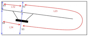
I sketched the proposed 17"x17"x48" enclosure as indicated in Post #47. It is a little off, but close enough for government work as we used to say. S3 and S4 are about 100cm^2 too large in the simulation, if you compare the outcome in Hornresp you'll see how small the difference is. (In the simulation Calculate SPL, back to Input, change S3 to 1200, S4 to 1300, Calculate and Compare Previous.)
Use the Filter Wizard/Active/Bandpass, and set the Lower Cutoff Hz to 40/Order 4/Linkwitz-Riley, and the Upper Cutoff Hz to 140/same order, and you are looking at a decent PA sub. It would take just a little bit of stuffing material in the S1/S2 area to flatten the response even more.
It may not be theoretically perfect, but this would work.
Regards,
Attachments
Last edited:
So... a quick peek at the schematic doesn't look like what I expected. Either I'm confused about what a ~.5 T flare looks like or this isn't an 'ideal' [max BW] TH.
I haven't historically had much luck trying to figure out why your sims look like they do based on the math you use but I'm open to discuss it. I think I know the simple answer but that hasn't done me much good so far.
Hyperbolic is so slow expanding that any < 1/2 WL long look conical in HR and since THs are typically only a 1/4 WL long.........
No, it's nowhere near a reactance annulled BLH/TH simply because the driver's specs are ill suited for one in the BW of interest.
Sorry, I'm not as long as Tom and other pro horn designers choose not to, though I'm curious what you think the simple answer is.
GM
O.K., here it is - The GBS15 (aka Grandpa's Booty Shaker).
I am not sure I am going to actually try to build this, but I would appreciate comments of the plus's and minus's of this design. Remember, I like criticism - it is the only way I will learn. I would love to hear any way I can make improvements. And if this design is a pile of shite, please let me know and I will start over again. Thanks.
Long story short, very nice, especially for a first try. But personally I probably wouldn't build this one.
Short story long, it doesn't compare especially favorably to a ported box a fraction of the size with the same driver.

The ported box shown is a bit less than 1/3 the size of the tapped horn. I didn't have a lot of time to spend on this so I didn't match f0, excursion, etc exactly and I didn't bother to make sure the ported box has an adequately sized port to ensure there is no velocity problems. Also the ported box is shown with a LOT more power than it's rated to handle. Depending on the type of music this may or may not be a problem. (Even the tapped horn is shown with more power than it's rated for to get it to xmax.) This power vs thermal compression issue is a whole topic in itself, and has to do with crest factor, duty cycle, and all kinds of other boring stuff. But theoretically drivers in tapped horns should be able to handle a bunch of power, they are basically sitting inside a fanned duct.
Tapped horn - 190 liters, 1250 watts
Ported box - 60 liters, 1800 watts
So if you compare at low power, like 1 watt, there's a dramatic sensitivity advantage for the big horn. But compared at xmax there's not really all that much difference. In the real world the tapped horn would probably dominate in a fashion not reflected in this simulation, but I prefer to build from a simulation that shows at least a bit more advantage compared to a much smaller ported box.
If you already owned the driver and had a stack of wood lying around waiting for a purpose, and the only goal was to get the most spl you could from these two ingredients without going full front loaded horn size, this would not be a bad choice. But I'd keep playing with the design and try other drivers to see what you can come up with. I think you can do better. Maybe try drivers that are known to work well in tapped horns, try using the drivers that Danley does for subs that play in the passband you are interested in.
Sorry, I'm not as long as Tom and other pro horn designers choose not to, though I'm curious what you think the simple answer is.
GM
That's EXACTLY what I thought the simple answer was / would be.
I'll figure it out one day.
Last edited:
+1, so I just 'ran the numbers', which you can compare to.
GM
GM, thanks for you input. So it looks to me like you version would work out to be slightly thinner, but about 10" longer.
It looks like both of our models are within about 10% variance except for S1, S2, and L23. I am curious on your thought process when you came up with this design, so let state what I believe you may have been thinking, and please correct me if I am wrong.
Lengthening L23 appears to give more low-end extension at the expense of a longer cab. Looks good to me.
Decreasing S2 appears to smooth out the frequency response slightly. It also increases the compression ratio. How did you chose S2 as the best compromise for this value?
Decreasing S1 appears to have little effect. My thinking on this is that is for this type of horn layout, you would set S2 first. Since the baffle board (horn segment divider) is one board, S2 would then become a pivot point. You would then adjust the far end of this board to be centered between the two opposing cabinet walls, and where ever the other end ended up being, that is your S1?
Posted below is a comparison of our two models. Yours is the black trace, mine is the gray trace.
Thanks for your time.
Attachments
I sketched the proposed 17"x17"x48" enclosure as indicated in Post #47. It may not be theoretically perfect, but this would work.
Wow, thanks! I feel like I have built something! What kind of 2D drafting program is that that you use? Very nice!
Thanks also for the tip on "Filter Wizard/Active/Bandpass." I hadn't noticed that feature and I can see how it would be very useful.
Long story short, very nice, especially for a first try. But personally I probably wouldn't build this one.
Short story long, it doesn't compare especially favorably to a ported box a fraction of the size with the same driver.
So if you compare at low power, like 1 watt, there's a dramatic sensitivity advantage for the big horn. But compared at xmax there's not really all that much difference. In the real world the tapped horn would probably dominate in a fashion not reflected in this simulation, but I prefer to build from a simulation that shows at least a bit more advantage compared to a much smaller ported box.
If you already owned the driver and had a stack of wood lying around waiting for a purpose, and the only goal was to get the most spl you could from these two ingredients without going full front loaded horn size, this would not be a bad choice. But I'd keep playing with the design and try other drivers to see what you can come up with. I think you can do better. Maybe try drivers that are known to work well in tapped horns, try using the drivers that Danley does for subs that play in the passband you are interested in.
Hey, thanks for your honest opinion, and for putting the work into the WinISD simulation. I will play around with this driver in WinISD tomorrow so I can better understand the benefits and drawback myself.
Also,thanks for also bringing up the subject of a 1 watt simulation vs. a max SPL (max Xmax) in a real world test. I will have to study that concept a bit more. I actually have some designs I am more proud of, but while they look decent in HR, actually turning a more complex fold pattern into a real cabinet is something I haven't quite mastered yet. That will be a 'question of the day' that will come up very shortly, maybe even tomorrow.
I didn't do anything in WinISD, I don't like WinISD. In the picture I posted the dark line in both the frequency response graph and the excursion graph is the tapped horn and the lighter grey line is the ported box. (Both simulated in Hornresp.)
As far as horn folding goes, you just go to the schematic drawing in Hornresp, click File - Export - Horn Data and use the cross sectional area vs path length information to draw out your horn. I draw mine out on paper, some people use Sketchup, some people use Excel, and there's even an Excel spreadsheet that will attempt to fold your horn for you. Some people draw the horn out as a straight horn on paper and cut it up into pieces and put it together like a puzzle. There are lots of options. There's even a few tricks you can use to make folding a lot easier than you probably think is possible. If I absolutely had to I could design and fold a horn complete with plans to build from in about an hour although I prefer not to rush the process.
If you want the fold to be accurate (so the sim matches the measurement of the finished product as closely as possible) you can study the advanced centerline method of horn folding. I did a recent study on advanced centerline vs centerline methods - Horn Folding - a brief study of the centerline vs advanced centerline method - and there's also a lot of other info in there about general horn folding considerations not specific to either method.
If you want links to some of the other folding methods I've mentioned I can point you in the right direction or you can look them up yourself.
Last edited:
Hi DHAA,
There was a lengthy discussion pertaining to losses and power compression in the "Collaborative Tapped horn project" thread, the main parties were Tom Danley, iand and cowanaudio, but others added interesting observations and experiences:
http://www.diyaudio.com/forums/subwoofers/97674-collaborative-tapped-horn-project-120.html
http://www.diyaudio.com/forums/subw...tive-tapped-horn-project-262.html#post1703164
http://www.diyaudio.com/forums/subw...tive-tapped-horn-project-263.html#post1703318
I'm sure there is more.
One of the things a TH has going for it v. a bass reflex is the size of the duct. At maximum power levels this will make a difference.
It seems that some people who have read through everything pertaining to tapped horns have not quite found the time to dig through this thread, so you'll be ahead of them.
Regards,
Hi DHAA,
Hope this is not getting to be too much, but just a few more little notes:
I use AutoCAD (Version 14, as long as I'm not forced to update at work). You'll either have to find a drafting program, or do it w/ paper and pencil. I liked the 48" dimension, great use of standard plywood.
In Post #54 you say: "...adjust the far end of this board to be centered between the two opposing cabinet walls..." that's close, but you have to take the equivalent duct length around the corner into consideration. Here is an example of Xoc1's very nice CAD work, see pdf in Post #734:
http://www.diyaudio.com/forums/subwoofers/170771-single-sheet-th-challenge-74.html
Bye the way, jbell's SS15, grown from the "Single Sheet TH challenge", is about as optimized a design as you are going to find (obviously, just my personal opinion).
Regards,
Last edited:
Thanks everyone for your comments and suggestions. This has been extremely helpful for me, I really appreciate everyones assistance. There will be no "Question of the Day" today, I have too much info to research and absorb already. I will be back tomorrow though!
Just a Guy - I have been using WinISD for ported cabs, I will have to try using Hornresp for that to gain more experience, especially since it would seem to be an easier and more accurate way to compare different models.
Also, thanks for the folding tips and Advanced Centerline link - that looks very interesting. If you are familiar with any other good links explaining how fold a HR horn design into an actual cabinet, I would appreciate your recommendations.
tb46 - Thanks for your tips and link recommendations too, that will also be very helpful. I used to be a pretty good draftsman back in the pencil, paper, T-square days, to it should be fairly easy to learn a digital drafting program.
I have already read some of the JBell SS15 posts. One of my experiments is taking that fold, substituting a different driver, and narrowing down the cabinet width. Let me check that over again (and apply what I have learned this week) and maybe that will be the next design I post.
- Status
- Not open for further replies.
- Home
- Loudspeakers
- Subwoofers
- Hornresp Brainiacs - Help an Old Man