What is the definition of a mediocre amplifier? Do you need a crazy high loop gain in the first place? Can you not aim for linearity instead? My personal aims are single digit ppm THD or lower (at least in sims as I don't have access to the necessary measurement equipment at present). Massive slew rate is unimportant to me (although this is said to be the CFA strength) as long as it is above 60v/us.
Linearity seems a safer way to proceed to me at present as you don't need to aim for high ULGFs which makes getting good PM/GM easier as the output stage pole becomes less significant.
Agree with your comments about compensation. Another personal goal is to reduce the TIS loading as much as possible. Thinking about using a diamond buffer straight after it in my latest experiment. Leaving the only significant loading being the lead-lag compensation to stabilise the miller loop.
Amplifiers that current limit when going from 8-4 ohm , I wouldn't waste time with them ...
You could add output devices (depending on the minimum load impedance) to lower the output stage open loop distortions to 0.01%, then you need only 40dB of loop gain at 60KHz, or an ULGF of 6MHz, still to high for a practical implementation.
But then 40dB loop gain at 60KHz with a decent phase margin can easily be considered as very high. Certainly beyond the reach of a standard compensated CFA.
The example is of course extreme, just to show the arithmetic of loop gains and distortions.
Well, I guess you just have to pick one's own definitions --- I don't think 40dB at 60KHz IS very high. Moderate, in fact. My goals are similar -- below -100dB distortion is my minimum for any audio product.... from recording microphone preamp to playback power amp output.... and everything in between. AND, low noise and all the rest.
If it takes a variety of compensation means and methods... cancellation included.... and matching and paralleled output devices -- so be it.
Anyone reading my input on several forums here know I am not interested in easy, cheap or mediocre performance.
Its good to know what the limitations are and where they are so we can find ways to over-come them... thru trickery, cleverness or brute force. Do what ever it takes to find the limits as we know them and one by one remove them or push the limits further away.
Thx-RNMarsh
Last edited:
Member
Joined 2009
Paid Member
My goals are similar -- below -100dB distortion is my minimum for any audio product.
 now that's a goal ! (emphasis added to the quote is mine)
Not everyone has to have the same goal (my ears aren't up to the challenge in this case and I find my listening pleasures can be met with much worse performance) but one thing about DIY is that we can define our own goals without the 'marketing department' chiming in.
Yes sometime someone has change his goal when he find that it is not what he wanted, silly, just like me self before. 😀
If I have non fatiguing, super beautiful sounded amp with good efficiency, I don't care its another things, even its reliabilty, I will care it for not blow up.
If I have non fatiguing, super beautiful sounded amp with good efficiency, I don't care its another things, even its reliabilty, I will care it for not blow up.
Last edited:
Not everyone has to have the same goal (my ears aren't up to the challenge in this case and I find my listening pleasures can be met with much worse performance) but one thing about DIY is that we can define our own goals without the 'marketing department' chiming in.
I'm having trouble .... I'm only going for -88db (.002% thd20). I hit
a limit of what I can do with single stage amplification.
The right combination of the FB resistor ratio (39R -1K) , gives the top
gain for my 992/1845 models. At this 66db OLG - is where I get the
above stated THD.
I have not tried a higher beta model (my zetex's) , this seem to be only
option short of adding another stage.
I'm debating whether shooting for less than .002% is really worthwhile
as the distortion components are mainly desirable H2 (-88db).
This would most likely "bloat" the device count , as well.
All the other factors , having the same THD... all frequencies/all loads ,
stability (even with NO compensation 😀) , speed , and PSRR have
been met.
Audio/circuit design is a multifaceted compromise ...
I think dadod/Mr. Marsh are way ahead ,
I just can't get those single digit PPM's. 😱
OS
What comp method are you using?
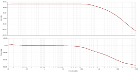
I can get .0008 at 400W 20k into 8 ohms using TPC. If I add AFEC I get to ~2.5ppm.
Note, this is at full power. My ULGF is a bit high at 2.5 MHz, but that can easily be trimmed down - THD will still be single digit ppm
That said, these are just fun numbers and in practicality not acheivable without a lot of work on the physical implementation.
I think anything below 50ppm at 20k full power is good, provided its low order harmonics - the challenge for good sound is mainly in the sepakers, room acoustics and recordings IMV - they need to catch up with amplifier SOTA.
Last edited:
What comp method are you using?
I can get .0008 at 400W 20k into 8 ohms using TPC. If I add AFEC I get to ~2.5ppm.
Note, this is at full power. My ULGF is a bit high at 2.5 MHz, but that can easily be trimmed down - THD will still be single digit ppm
That said, these are just fun numbers and in practicality not acheivable without a lot of work on the physical implementation.
I think anything below 50ppm at 20k full power is good, provided its low order harmonics - the challenge for good sound is mainly in the sepakers, room acoustics and recordings IMV - they need to catch up with amplifier SOTA.
Really , Sota amp huh , Bonsai special .... 🙂
What comp method are you using?
I can get .0008 at 400W 20k into 8 ohms using TPC. If I add AFEC I get to ~2.5ppm.
Note, this is at full power. My ULGF is a bit high at 2.5 MHz, but that can easily be trimmed down - THD will still be single digit ppm
That said, these are just fun numbers and in practicality not acheivable without a lot of work on the physical implementation.
😎🙂
Here is an HP oscillator/generator source that was spec'ed at .0018% THD+N. With some tweaking it can do much better.... this is thru several opamps, caps and other parts selection and retuning. It can be used to test amps etc and only cost about 100-200 USD used. The down side is -- To tune it and accurately know the distortion levels requires either a ShibaSoku AD725D analyzer or an A-Precision 2722, though. Slightly higher cost: About $60K USD, new for both. However, you can copy process and then tune for best null. Even if you cant measure the generator's THD/N accurately, it will be below -100dB after the mods.
Click on picture and zoom in -- Using a Panasonic Industrial AP-7722A

Thx-RNMarsh
Last edited:
When you have a good SIM circuit at or below .001% or -100dB then you need to be able to verify and measure it. There are several very good people on other forums here which are working in parallel with you to get low cost, accurate means to measure
<-100dB for your best DIY designs and efforts.
Thx-RNMarsh
<-100dB for your best DIY designs and efforts.
Thx-RNMarsh
Last edited:
Really , Sota amp huh , Bonsai special .... 🙂
LOL. I have to build it now. But, I have another big project running so it will have to wait.
Here's an interesting example of what some of you keep on calling 'CFA'- a compound emitter follower with gain output stage with feedback from the Re's .
It is of course true current feedback in the original meaning, as the feedback signal is a sample of the output current.
Comments?
Jan
It is of course true current feedback in the original meaning, as the feedback signal is a sample of the output current.
Comments?
Jan
Attachments
Last edited:
Comments?
It's in different league than CFAs discussed in this thread. Throw it away 🙂
 could you help?
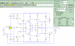
It's in different league than CFAs discussed in this thread. Throw it away 🙂
So far it's the only TRUE CFA I've seen here. You wimps! 😉
Jan
Jan so you believe that the current sampling of the output emitter-resistor is of significance, compared to the voltage driven current modulation over the 100 ohms gnd resistors in the feedback loop...??
still a voltage sampling/current injection feedback circuit.
still a voltage sampling/current injection feedback circuit.
Here's an interesting example of what some of you keep on calling 'CFA'- a compound emitter follower with gain output stage with feedback from the Re's .
It is of course true current feedback in the original meaning, as the feedback signal is a sample of the output current.
Comments?
Jan
Jan, let me try to summarize it
What youve you've described is a current output amplifier, as opposed to a voltage output amplifier. Nothing to do with feedback, but simply the output controlled dimension.
You can do both voltage output or current output with CFA and VFA. You can also do them inverting and non inverting mode.
In doing so, you will have covered all 4 of the canonical feedback topologies - see Leach for example for a good summary of this.
Completely separate from this is the amplifier topology: CFA or VFA. VFA inv input is a high impedance node and responds to voltage. CFA inv input responds to current. Further, derivation of the gain equations (CFA or VFA) are different, although they reduce to the same for closed loop gain in both the inverting and non inverting configuration. This implies, correctly, that the internal operation of said CFA and VFA devices are different internally.
Hopefully I've summarized it succinctly.
🙂
Last edited:
What youve you've described is a current output amplifier, as opposed to a voltage output amplifier. Nothing to do with feedback, but simply the output controlled dimension.
Incorrect, on both counts:
- It is not a current output amplifier. You missed the global feedback loop to the input op amp. The output current feedback (it's actually series-series feedback) loop is local.
- Feedback (type) is all about sampling and controlled dimension.
- Home
- Amplifiers
- Solid State
- CFA Topology Audio Amplifiers