Let the amplifier (cfa) be "controversial" in my living room.
Hopefully , grounded in reality.
My analogy of this thread to the "blowtorch" is quite
appropriate , at least it has not digressed to moderator intervention.
Bonsai , your info... (PDF's) are very helpful.
now , "I know enough to be dangerous" 😀
OS
Hopefully , grounded in reality.
My analogy of this thread to the "blowtorch" is quite
appropriate , at least it has not digressed to moderator intervention.
Bonsai , your info... (PDF's) are very helpful.
now , "I know enough to be dangerous" 😀
OS
P.S. I hope not!
Current gets out of black boxes too. Put a 1000V/us ramp on the input with for instance 10pF comp cap. That's 10mA of current that has to flow in or out of the inverting input and the drop in any impedance from it to ground must be accounted for. I think your idea of "black box" is too narrow, if an amp delivers 1A to a load where does the current come from?
In the first case the compensation is usually a shunt C to ground the displacement current in C finds its way to ground and that loop has no problem with KVL, KCL, or charge conservation.
EDIT - BTW I agree on several other points. It is trivial to add a diamond buffer plus resistor to a "CFA" to get a slew on demand input. So say you pick a closed-loop gain and a resistor and comp cap for the same closed-loop BW. You are designing discrete amplifiers for a fixed application and you have access to everything. The resulting CFA vs VFA comparison would show little difference in performance in the direct signal path. I would look elsewhere, PSRR, CMRR, EMI for differences.
I agree, the inverting input current flows through the compensation cap to the ground, but then this implies a ground connection in the black box which is, to me, quite unorthodox for a "black box". An "op amp" does not assume such a connection.
The description of the design process for a discrete amp is exactly what I had in mind. CFAs for audio, that's an illusion, at least due to the pretty high closed loop gain.
There is an annoying confusion, between the "CFA properties" and the high slew rate. They have pretty much nothing in common, they are coupled when discussing a particular topology of the amplifier. I also agree that much more has to be considered for a fair apple to apple comparison of VFAs vs. CFAs for audio. Myself, I would not sacrifice a drop of PSRR and CMRR for a huge slew rate.
I also agree this discussion is pretty much useless and goes nowhere. Sorry for stirring again the pot, but I can't stand half baked fetishes.
I am not debating the CFA properties, only that, strictly from a feedback perspective, the "CFA" denomination is confusing and ultimately incorrect. "CFA" is related to a particular "op amp" topology and open loop property, and not to a particular feedback type/topology.
You are debating the explanation of the CFA properties.
I gave a source early on here that derived a more accurate SPICE model to use and thoroughly explains the CFA. Here it is again: Emerging Techniques For High Frequency BJT Amplifier Design: A Current-Mode perspective. C.Toumazou, J.Lidgey, and A.Payne. 1994. (95 pages) Parchment Press Ltd, Oxford.
The detailed explanation of a CFA can be found there and other places in great detail for the intellectuals.
Thinking out loud --- I am pretty amazed that one would even attempt to debate or refute any designers from the IC industry on the difference and their explanation of how VFA and CFA works. Shouldn't they know... they design and make both types and combo types. How can they do that without knowing the difference and being able to explain it?
For myself, concepts and ideas and analogies are good enough... simplify to get the main points across..... some simplified engineering formulas etc. I want the big picture and the interrelated issues. When SW isn't dumbing down, he can easily go way over My head on the subject details. Fortunately, I/we don't need to know that level of detail. But I/we do seriously appreciate and need specialists and give careful consideration to their input.
So, what do you think might be a benefit to an CFA audio amplifier?
Thx-RNMarsh
Last edited:
You are debating the explanation of the CFA properties.
Fortunately, I/we don't need to know that level of detail.
So, what do you think might be a benefit to an CFA audio amplifier?
In this order: yes, if you don't need then don't read such details, none.
In this order: yes, if you don't need then don't read such details, none.
Ok fair enough. done with that subject then. What about compensation? is it easier or the same? stability, hf distortion et al.
Thx-RNMarsh
Last edited:
To some guys we all here represent a silent threat constantly speaking of CFA in dedicated thread, even dare to build damn things and claim they sound nice. Just don't let their noise distract you from realizing the amp from post #2623 soon.Let the amplifier (cfa) be "controversial" in my living room.
Hopefully , grounded in reality.
My analogy of this thread to the "blowtorch" is quite
appropriate , at least it has not digressed to moderator intervention.
Bonsai , your info... (PDF's) are very helpful.
now , "I know enough to be dangerous" 😀
OS

EF3 is .04-.05% thd20, regardless of load. EF2 is the same at 8R ... gets worse with load.
Class A genesis stealth OPS is .001%.
Xover dist. is 95% of the THD. That is why Class A has a "following" and
all those OEM's pursue "non-switching OPS's".
OS
.001% can you supply schematic? or is this a joke?
Thx-RNMarsh
What about compensation? is it easier or the same? stability, hf distortion et al.
IMO, for discrete amplifiers:
In this order: more difficult to implement compensation (because a node is almost always going to be low impedance high order compensation is more difficult, and being usually single stage gain it requires almost always an extra Miller loop compensation), stability (that is, the gain and phase margins for a similar compensation network) the same, hence HF distortions the same.
Of course, if you believe that 0.01% distortions is all audio ever needs, then, VFA or CFA, it's all the same. CFAs trend to be simpler, I have to plead guilty here for not being able to understand why "simple is better" other than for commercial/subjective reasons. I have never heard of any proof, other than anecdotic, that the sound quality would be inverse proportional to the complexity. YMMV, though.
So, what do you think might be a benefit to an CFA audio amplifier?
Thx-RNMarsh
If the designer can set all the parameters of the amplifier and is designing to a set goal of say 23dB closed-loop gain then there could possibly be no benefit.
Integrated CFA's gained popularity in high speed A/D buffering and video where a small range of relatively low gains (6-20db) had relatively similar performance with less need for customization (i.e. work).
BTW - some of those distortion cancellation circuits work into only one particular resistive load, the performance with a real speaker could make them pretty much why bother. Same with degenerated current mirrors, if the resistive part vs the Vbe part are not in exactly the same ratio your .01% can quickly become 1%.
Last edited:
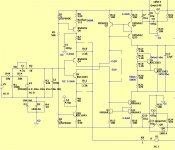
What compensation ?
I don't quite understand ,
I used a wilson current mirror VAS , driven by a basic
CFA.
I removed all compensation .... and it is stable !
The circuit is the same , except for the wilson.
very strange ?? 😕
I ABSOLUTELY can not do this on any of my dozens of VFA
simulations or on a real amp (instant smoking zoble resistor).
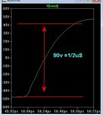
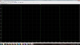
This is the fastest ...180V/us with feedback values shown , raise
the device currents to 4ma - 250+ . SW is perfect (tiny overshoot)
OS
I don't quite understand ,
I used a wilson current mirror VAS , driven by a basic
CFA.
I removed all compensation .... and it is stable !
The circuit is the same , except for the wilson.
very strange ?? 😕
I ABSOLUTELY can not do this on any of my dozens of VFA
simulations or on a real amp (instant smoking zoble resistor).
This is the fastest ...180V/us with feedback values shown , raise
the device currents to 4ma - 250+ . SW is perfect (tiny overshoot)
OS
Attachments
.001% can you supply schematic? or is this a joke?
Thx-RNMarsh
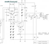
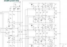
I'm not joking , I did post the stealth schema.
It did .004% on LT at 100V/20k. .001% @ 20v p-p 20k.
Genesis also stated a similar figure in the literature.
The complete amp was 4 amps in parallel.
I HAD to simulate it to fix it . the schema has some resistors with (???).
I suppose it is the 8000$ secret - but I succeeded. 🙂
PS - the originals below ...
OS
Attachments
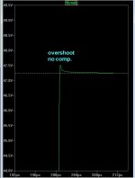
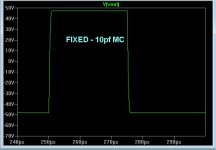
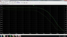
With a widlar mirror i suspect your overshoot to disappear
That's with no comp. !! The widlar is slower.
10pF MC kills the overshoot nicely.
Still 150V/us with the MC.
The "need for speed" 😀 .
OS
Attachments
Last edited:
Ostripper, may I ask you how you make the LT-spice make Bodeplot,
Reason I suggest the Widlar mirror is that I have seen some overshoot in the current mirrors i have uses in some of my Phono-stages, the Slower mirror cured the oscillation tendensy
Reason I suggest the Widlar mirror is that I have seen some overshoot in the current mirrors i have uses in some of my Phono-stages, the Slower mirror cured the oscillation tendensy
Last edited:
Ostripper, may I ask you how you make the LT-spice make Bodeplot,
Reason I suggest the Widlar mirror is that I have seen some overshoot in the current mirrors i have uses in some of my Phono-stages, the Slower mirror cures the oscillation tendensy
Which bodeplot ? I do loop gain,PSRR, bandwidth... and a few others
for "problem" circuits.
OS
Which bodeplot ? I do loop gain,PSRR, bandwidth... and a few others
for "problem" circuits.
OS
Os, way you don't use Tian probe for the Lopp Gain simulation. Simple voltage probe (Middlebrok) is not good enough for low impedance feedback.
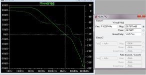
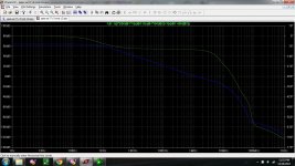
both the loop gain and the PSSR are interesting
loop gain is easy , just break the NFB with a V source (below) ,
add commands. done - below 2 is the output.
Notice the effect of the 10p MC on both the 0db freq.(UG) and
the extension of the phase margin plot. Cause and effect ...
this is what "took out" the overshoot.
OS
Attachments


Os, way you don't use Tian probe for the Lopp Gain simulation. Simple voltage probe (Middlebrok) is not good enough for low impedance feedback.
"not good enough" ? will it not predict stability ?
Transient /overshoot seemed to be reflected by the
middlebrook bode response . But , this is CFA .. I will use tian 🙂 .
OS
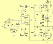
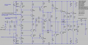
What do you think about the following modified version of Apex AX17?
THD at 20khz with 30V output is 0.004%, SR about 120V/us.
LG phase margin is 80 degree, but, from the OLG bode plot is seems to be unstable, is there a problem in the schematic design?
Is it CFA?
Thank you!
PCB-s are already made, construction is next 😀
THD at 20khz with 30V output is 0.004%, SR about 120V/us.
LG phase margin is 80 degree, but, from the OLG bode plot is seems to be unstable, is there a problem in the schematic design?
Is it CFA?
Thank you!
PCB-s are already made, construction is next 😀
Attachments
- Home
- Amplifiers
- Solid State
- CFA Topology Audio Amplifiers