It's just a point to keep things in balance. As a designer I think I you can stress one parameter over another needlessly. I would not for example target 1000 V/us, and I don't target 50 ppb distortion because in both cases it's wasted effort and drives uneccessarily complexity.
This is exactly correct. Same for those who relentlessly pursue ultra low noise circuits at the expense of other issues. Its all about balance. But good engineering can usually obtain great results across the board.
Cheers,
Bob
If we think its necessary to test for thd and IM using high freqs (10Khz-20KHz), then it implies a linear BW much greater than 20KHz.
The SR might be more in line with the other tests we do..... maybe a SR of 40Khz signal or higher. Minimum of 2.5 - 5v/usec /peak V is what I use.
Push yourself a little more -- If you want a yard stick; My own amp designs will do full/high power at 100KHz at low thd (not SIM). Why not? Isn't that hard to do. Push the envelope to see what is possible. We don't have to sell them and make money here. Its R&D.
But, If you want to just do 1.25v/usec SR, it wont be a disaster/failure either......
Thx-RNMarsh
Richard,
Bear in mind that 1.25V/us per peak volt is a 200kHz power bandwidth. That is the MINIMUM I like to see. It is easy to beat that metric, and it is regularly done by competent designers. But SR by itself does not guarantee superb high-frequency sound quality. Dynamic crossover distortion in the output stage will still be a potential issue even if the SR is very, very high. If you focus only on slew rate, you are making a big mistake.
Cheers,
Bob
"Balanced" Results ...
From my VFA perspective - the example amp (below 1-final) is a very nice performer
(simulated).
UG (below 2) is typical of my "fastest" VFA ,LF OL gain is nowhere where it is in
a typical "blameless" ... but it is not one .
. Slew is much better , 80K square waves are perfect. THD stays at .005% from 20hz to 40Khz before rising (3R) ,
and with the triple OP , 2R - 8R ... everything stays the same. 🙂
I don't think matching will be a real issue - swapping dissimilar models for
the input pair did not produce as much offset as in a classical (VFA) differential.
Adjusting the positive CCS nulls the DC perfectly.
I would build this just to A/B it to the "badger" or the VFA harmon/kardon 680
the triple is based on.
OS
Attachments

Richard,
Bear in mind that 1.25V/us per peak volt is a 200kHz power bandwidth. That is the MINIMUM I like to see. It is easy to beat that metric, and it is regularly done by competent designers. But SR by itself does not guarantee superb high-frequency sound quality. Dynamic crossover distortion in the output stage will still be a potential issue even if the SR is very, very high. If you focus only on slew rate, you are making a big mistake.
Cheers,
Bob
I understand your point. In fact, here at the CFA discussion we got as far along in topology up to the OPS. You suggested a triple early on in this. But, the OPS is not unique to VFA or CFA. Its optimization will benefit both types.
SR is a separate subject from OPS. It may be that OPS is the limiting stage.
I have not found that low noise and low distortion and high slew rate to be impossible nor to affect one another negatively. You can have it all to a large(r) extent. And, it doesn't cost more.
Thx-RNMarsh
Last edited:
If we made CFA and VFA with SR, THD, IM/TIM, PSRR, Frequency response, power, damping factor, etc to almost identical, will both sound identical/same too?
If we made CFA and VFA with SR, THD, IM/TIM, PSRR, Frequency response, power, damping factor, etc to almost identical, will both sound identical/same too?
If every single thing we can measure was the same... . That would also include the harmonic structure under dynamic conditions..... clipping distortion produced was the same etc.... identical is identical... they would sound the same. But then, two identical VFA would do the same thing and would be easier.
Thx-RNMarsh
Last edited:
I would build this just to A/B it to the "badger" or the VFA harmon/kardon 680
the triple is based on.
OS
Nice. I am waiting the result.
If every single thing we can measure was the same... . That would also include the harmonic structure under dynamic conditions..... clipping distortion produced was the same etc.... identical is identical... they would sound the same. But then, two identical VFA would do the same thing and would be easier.
Thx-RNMarsh
I see. I am curious about slew rate. If we made 2 identical VFA except the value of miller/TIC/TIM/etc compensation then one amp have 2x slew rate of other one. The one with minimum slew rate has 200kHz power bandwidth. Will both amp sound same?
2.5v/usec/peak v as the minimum is not hard to do.
-RNM
Agree
there's no reason to believe Carver's SS amp and Stereophile's selection of a "STOA" tube amp had the same slew rate - but we all know how that listening comparison by professional "Golden Ears" came out
there really is no evidence for slew rate beyond a adequate margin for music recording playback from our all <100 kHz BW media being necessary
there really is no evidence for slew rate beyond a adequate margin for music recording playback from our all <100 kHz BW media being necessary
there really is no evidence for slew rate beyond a adequate margin for music recording playback from our all <100 kHz BW media being necessary
yes, there is no evidence.... so we should do the work and be able to say there now is evidence that - blah blah blah. Then it is done. Check!
I would say - as I do with distortion - that the accumulated affects are what we hear when we listen to music..... not a single stage or amp but from microphone to speaker.... the whole recording and playback system is what we are listening to. That is why we need wider BW and lower distortion in every stage than what we can hear from just one amp/stage in the entire chain.
Thx-RNMarsh
Last edited:
Yes, there is no evidence...untill you'll make your own listening tests to figure out by yourself.there really is no evidence for slew rate beyond a adequate margin for music recording playback from our all <100 kHz BW media being necessary
As well as there is no evidence for an input low pass filter with very high bandwidths amps... etc. etc.
I wonder of the position of the handle of naysayers, in this thread. They don't have experience of CFAs, they don't have listened CFAs, they don't have made listening comparisons to learn what is specific in this topology and figure out what is the 'signature' if any... And they don't believe in what says other designers that had done all those experiences during decades or even in hundreds of DIYers or 'audiophile' reports.
They pretend to be 'objectivist', but, look, this position is just insane.
They don't make their own tests, they ask others for demonstrations (Lazy ?), they don't believe in them, pretending others are stupid.
What is this, philosophy or technology ?
In fact, they just produce words...blabla.... noise...
Sorry, Hifi is not a science with ideal components designed by computers and listened by robots or measurement instruments.
Sorry, hifi design require a minimum of personal involvement in real world.
distortion cancellation -
To reduce distortion, some feedback from drain to gate reduces distortion..... thus, this simple approach. Can it be SIM and improved? Note the thd improvement.... only .003% without any gnfb applied.
Any similar ideas for OPS?
View attachment OPS distortion cancellation.pdf
Thx-RNMarsh
To reduce distortion, some feedback from drain to gate reduces distortion..... thus, this simple approach. Can it be SIM and improved? Note the thd improvement.... only .003% without any gnfb applied.
Any similar ideas for OPS?
View attachment OPS distortion cancellation.pdf
Thx-RNMarsh
Last edited:
Playing around with my new toy (CFA) got me thinking. It performs nearly identical
to my GLA VFA with worse PSSR but better slew.
The VFA just senses voltage at the feedback node.
The CFA (might) be
using both the interaction of the OP with the dynamic load of the loudspeaker
and the voltage information to form the FB signal.
I can simulate a "fake" loudspeaker , but not a real one that compresses air.
This is the only conclusion I can come to as to why a CFA might sound
"different / more accurate".
I'm short 2 amplifiers in the house. 4 pairs of speakers , only 2 amps. 🙁
So .... it must be built.
OS
I remember that you have standard (tho very general) on phase response. How they are compared 😉to my GLA VFA with worse PSSR but better slew.
So you'll know if CFA works with wider variation of speakers (but it can be seen from simulation) 🙂4 pairs of speakers
To reduce distortion, some feedback from drain to gate reduces distortion..... thus, this simple approach. Can it be SIM and improved? Note the thd improvement.... only .003% without any gnfb applied.
Any similar ideas for OPS?
View attachment 387723
Thx-RNMarsh
That is an interesting "clip"
I see this "trick" in some old classic japanese amps. (old Nakamichi's)
Have simulated AND built it , as well. It does work.
Yamaha "HCA" -"non-switching" -"super A"... etc , this is the more advanced
marketing "hype" for the active versions.
In D. Selfs new book , all are described ... some
are debunked.
It may seem simple with just some passives ... in reality much harder
to implement.
PS - never tried it with FET's.
OS
I remember that you have standard (tho very general) on phase response. How they are compared 😉
So you'll know if CFA works with wider variation of speakers (but it can be seen from simulation) 🙂
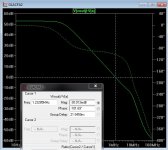
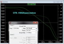
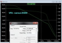
CFA has real short group delay (plot 1)
VFA is plot 2. It is the sansui Z3900.
Either amp will work with any of my speakers - even 2 pairs in parallel 😀.
OS
Attachments
CFA has real short group delay (plot 1)
Do you think it doesn't matter? 🙂)
- Home
- Amplifiers
- Solid State
- CFA Topology Audio Amplifiers