It would be interesting to see measurements from several rooms using corner horns. 1/24 oct smoothing please. And an ETC would be nice to.
If they work well, the frequency response should be very even.
Why? There's still a floor, ceiling and wall.
Room response doesn't tell all, but with ETC, STI etc. and decay sonogram we can evaluate how the sound "sounds" Delay and level (D/R ratio) of reflections would be very different from "normal" freestanding speakers.
Room response vs. anechoid/1 meter response reveals room effects to an deducated eye.
Ears+brain make a very delicate analysis system, but it's validity and reliability is poor, benchmarking with peers difficult and poor.
Room response vs. anechoid/1 meter response reveals room effects to an deducated eye.
Ears+brain make a very delicate analysis system, but it's validity and reliability is poor, benchmarking with peers difficult and poor.
It has a pretty constant directivity down to schroeder. There's huge difference between that and a speaker with CD only down to 1000-1200 Hz. The response becomes much more even. CBT36 does that by the way and yields an encredible flat response down to about 200 Hz.Why? There's still a floor, ceiling and wall.
The corner horn will do the same and a horn lense can also greatly minimize vertical reflections. A round horn will however not to do it.
Why? There's still a floor, ceiling and wall.
For the majority of systems placed in a corner this is true. For example a stock K horn would have side wall reflections from mid and top horn just the same as any other speaker would. For the special designs that Tom and Wayne are talking about you can meld the system into the 3 surfaces of the corner and make those planes disappear, at least for the first bounce.
Getting rid of the first boundary bounce can be achieved in simpler ways, though. An Allison approach of woofer near the boundary and mid well spaced away does as well in dealing with floor and back wall reflections, and works in a greater range of rooms.
The constant directivity attribute of ideal corner placement may or may not be a benefit. It seems to me that trihedral placement actually throws away your directivity. Bose's first product had a number of full range units in a corner placed 1/8th of a sphere. How would that measure any differently?
Corner placement makes your source omnidirectional.
David S
Last edited:
It mostly have to do with the fact that the room functions as a waveguide, and thus yielding a constant directivity down to schroeder.
It's an old Klipsch design. Nothing new under the sun. Thank you Paul!

It's an old Klipsch design. Nothing new under the sun. Thank you Paul!
Dave, true omni but no "backwash"
It mostly have to do with the fact that the room functions as a waveguide, and thus yielding a constant directivity down to schroeder.
It's an old Klipsch design. Nothing new under the sun. Thank you Paul!
Nope, it's a bit of a paradox but anything with directivity wider than the corner becomes omnidirectional when placed in the corner.
For the majority of systems placed in a corner this is true. For example a stock K horn would have side wall reflections from mid and top horn just the same as any other speaker would. For the special designs that Tom and Wayne are talking about you can meld the system into the 3 surfaces of the corner and make those planes disappear, at least for the first bounce.
Sure but again, who wants the sound to come from the floor or ceiling???
Getting rid of the first boundary bounce can be achieved in simpler ways, though. An Allison approach of woofer near the boundary and mid well spaced away does as well in dealing with floor and back wall reflections, and works in a greater range of rooms.
How would you prevent lobing? I've tried a mid-woofer at the floor/front wall corner with the tweeter at ear height with not much success.
Personally, I'd be very happy with really good sound that is perceived as coming from the wall-ceiling junction height (or from the angle between me and junction).
You need a 3-way, if not 4-way.How would you prevent lobing? I've tried a mid-woofer at the floor/front wall corner with the tweeter at ear height with not much success.
Last edited:
How would you prevent lobing? I've tried a mid-woofer at the floor/front wall corner with the tweeter at ear height with not much success.
I agree it is difficult with a 2 way, but it works well with 3 ways.
The basic premise is to put a driver near the floor and a second driver at ear level. The one near the floor will have its primary floor bounce dip fairly high up. The upper unit will have its first dip fairly low down. All you have to do is crossover at a frequency between the 2 primary dips.
David
I can't see it working well with a typical 2 way at all, the physical geometry and crossover frequencies just don't work out.I agree it is difficult with a 2 way, but it works well with 3 ways.
The basic premise is to put a driver near the floor and a second driver at ear level. The one near the floor will have its primary floor bounce dip fairly high up. The upper unit will have its first dip fairly low down. All you have to do is crossover at a frequency between the 2 primary dips.
You want the lowest frequency driver more or less at the floor, and the highest frequency driver at nominal ear level (~1m) for best imaging, that pretty much dictates a low crossover frequency that don't work with most 2 way systems.
When you weigh all the factors together you come up with an optimal crossover frequency of around 200-300Hz from the woofer to the next driver up for a "woofer at the floor" design.
So unless you're doing a "FAST" system with something like a full range driver at ear height crossed over to a helper "woofer" at the floor at around 200-300Hz then 3 way is the only thing that is going to work. (Even a large 2 way CD horn and woofer system isn't going to cross over that low)
With a 3 way design it works very well. Tweeter at ear level, midrange as close as possible underneath the tweeter then a large gap to the woofer at the floor.
With those dimensions it works out to be about a half wavelength between the woofer and midrange at a 250Hz crossover frequency - enough to give a useful increase in vertical directivity in the low midrange region but without forming multiple lobes.
Last edited:
The basic premise is to put a driver near the floor and a second driver at ear level. The one near the floor will have its primary floor bounce dip fairly high up. The upper unit will have its first dip fairly low down. All you have to do is crossover at a frequency between the 2 primary dips.
When you weigh all the factors together you come up with an optimal crossover frequency of around 200-300Hz from the woofer to the next driver up for a "woofer at the floor" design.
With a 3 way design it works very well. Tweeter at ear level, midrange as close as possible underneath the tweeter then a large gap to the woofer at the floor.
With those dimensions it works out to be about a half wavelength between the woofer and midrange at a 250Hz crossover frequency - enough to give a useful increase in vertical directivity in the low midrange region but without forming multiple lobes.
Exactly. This is the approach I've found works best as well.
The problem with this approach is that in most cases, the floor bounce frequency of the midrange is well above what is needed to get a low enough crossover frequency to allow for a really wide driver spacing and thus bounce nulls really far apart in frequency.
For example: According to BoxyCad, for a listening height of 95cm, a midrange height of 85cm and a listening distance of 2.5m (which should represent a fairly common arrangement), the midrange bounce occurs at 300Hz. For lower midrange positions and/or greater listening distances, it will be even higher.
If you want to place the crossover frequency at the geoemetric mean of the midrange and woofer bounce nulls and at the same time keep CTC spacing within 1/2 wavelength of the crossover frequency, the solutions you arrive at iteratively all fall into a region of only 30-40cm CTC distance and a crossover frequency between 400-600Hz – not very far away from either of the bounces (and almost exactly double of what has been mentioned).
It baffles me that the "classic" Allison approach is almost always being recommended with driver spacings much larger and crossover frequencies much lower than that. I can only see that working when you accept a lot more lobing – or am I missing something here?
Suits me too, Sir! Steep xo slopes offered by modern dsp's help here too.
My exprience with a 4-way are satisfactory. We need at least 2m distance, my usual distance is 2.5m (8') Vertical directivity humps and lobing will not be a problem easily, these malicies are overestablished generally in discussions.
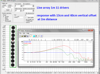
Actually it would be rather difficult to make a multiway speaker to present lobing -an example here. Lobing is a real phenomenom with line arrays without shading or curvature (see attachment).
Here a real case of lobing - a line array KS-160-21 by "Kimmosto" Listeners liked the speaker - lobing was not percepted!
My exprience with a 4-way are satisfactory. We need at least 2m distance, my usual distance is 2.5m (8') Vertical directivity humps and lobing will not be a problem easily, these malicies are overestablished generally in discussions.
Actually it would be rather difficult to make a multiway speaker to present lobing -an example here. Lobing is a real phenomenom with line arrays without shading or curvature (see attachment).
Here a real case of lobing - a line array KS-160-21 by "Kimmosto" Listeners liked the speaker - lobing was not percepted!
An externally hosted image should be here but it was not working when we last tested it.
Attachments
Last edited:
According to BoxyCad, for a listening height of 95cm, a midrange height of 85cm and a listening distance of 2.5m (which should represent a fairly common arrangement), the midrange bounce occurs at 300Hz.
If crossover is made in this ~300Hz region, then floor bounce is mitigated.
The woofer has no floor bounce, because it is acoustically close to the floor. The midrange does, but self-interference is at the edge of its passband.
Also woofer and midrange overlap in this area, so where one is cancelled by self-interference, the other is not.
The midrange horn is close enough to the walls that horizontal self-interference is a non-issue, and its relationship with the woofer mitigates vertical self-interference.
And since the path length deltas between listener and both woofer and midrange are close to the same, lobing is literally outside the room. The relatively low crossover point ensures this.
What you're missing is that the classic "floor bounce" - eg the path differential between the direct signal and a single bounce from the floor in front of the speaker to the listener - is only one of many, many boundary reflections occurring, and it also doesn't take into account room modes.The problem with this approach is that in most cases, the floor bounce frequency of the midrange is well above what is needed to get a low enough crossover frequency to allow for a really wide driver spacing and thus bounce nulls really far apart in frequency.
For example: According to BoxyCad, for a listening height of 95cm, a midrange height of 85cm and a listening distance of 2.5m (which should represent a fairly common arrangement), the midrange bounce occurs at 300Hz. For lower midrange positions and/or greater listening distances, it will be even higher.
If you want to place the crossover frequency at the geoemetric mean of the midrange and woofer bounce nulls and at the same time keep CTC spacing within 1/2 wavelength of the crossover frequency, the solutions you arrive at iteratively all fall into a region of only 30-40cm CTC distance and a crossover frequency between 400-600Hz – not very far away from either of the bounces (and almost exactly double of what has been mentioned).
It baffles me that the "classic" Allison approach is almost always being recommended with driver spacings much larger and crossover frequencies much lower than that. I can only see that working when you accept a lot more lobing – or am I missing something here?
The calculated floor bounce notch as you describe it typically isn't even measurable at 2.5 metres in amongst the "noise" of all the other adding and subtracting reflections from various boundaries. Up closer you can measure it but I've not been able to measure it at 2.5 metres in a typical size room.
The worst offender by far for upper bass / lower midrange notches is actually the 2nd harmonic (1 wavelength) floor to ceiling mode - which on a typical 2.4 metre / 8 foot ceiling occurs at about 140Hz. 1/4 of that floor to ceiling height is 0.6 metres which is not too far from the typical midwoofer height of many speakers, because its a 2nd harmonic mode 1/4 of the height (as well as half and 3/4) is a null point thus dropping the midwoofer right into a deep notch at that frequency.
This notch is very real, and unlike "floor bounce" which changes in frequency with listening distance, is at the same frequency and in evidence pretty much anywhere in the room. (The self interference causes an actual loss in power response)
A woofer at the floor fully excites all floor to ceiling modes and thus does not exhibit any response notches due to the floor/ceiling modes regardless of the height of the ceiling. (Whereas a higher mounted woofer will not only exhibit notches due to vertical modes, they will be at different frequencies for different ceiling heights, thus no universal EQ correction exists)
Sure, there are other notches from sidewall and front wall cancellation but its still a big improvement. As Speaker Dave loves to say, don't make perfect the enemy of good. 😀
Although your calculation based solely on classic floor bounce suggests 200-300Hz is too low, when all reflections from typical room geometry and speaker placement is considered it typically works out the best.
It's easy to test empirically too, something I've done a number of times - measure the response of the floor mounted woofer and the high up midrange without any crossovers at a typical 1 metre high 2.5 metre away listening position with the speakers in their normal optimal location.
Looking at the two responses overlaid will immediately show the best crossover frequency to minimise floorbounce / boundary cancellation etc... With an 85cm high midrange all the worst notches occur below about 200Hz.
Wayne also rightly points out that even if a significant notch was occurring at the listening position for the midrange driver at 300Hz, through the overlap region there will still be a big improvement as the notches from a single driver tend to be very deep (20db or more) while at the overlap frequency at worst you will lose 6dB even if one driver is not contributing at all at that frequency.
A 12db/oct crossover at say 250Hz has a wide enough overlap that deep notches from an individual driver will be mitigated quite some way on either side of the crossover frequency. (Perhaps an argument against making this crossover point too steep) If your drivers are spaced at half a wavelength at crossover there is also enough directivity through the overlap region to reduce the strength of the floor bounce somewhat through directivity alone.
Another interesting thing about a half wavelength spacing is that near the crossover frequency where the drivers are at a half wavelength spacing in theory directly up and down towards the ceiling and floor is a directivity null point, meaning that any floor/ceiling modes that occur through this range will have little if any effect.
The low woofer high midrange approach works really well in practice, there are a lot of different factors involved not just the single floor bounce distance differential calculation.
Last edited:
True Dat. (-:ha, "simply".
It seems to me however that this speaker design or variations of it becoming standard fare is almost inevitable. The positives far outweigh the negatives.
- Status
- Not open for further replies.
- Home
- Loudspeakers
- Multi-Way
- Uniform Directivity - How important is it?