I just discover these parts as announced by Owen, so I looked at the DS.The TPS7A3301 comes in a TO220-7 package(KC) There is no KC package for the TPS7A4701, it only comes in the 5mm QFN package, which is a shame.
I wonder if you can float the supply for the TPS7A3301?
If so, one thing I see that is nice is that the feedback R values are high compared to a LM337. Feedback current has be >5uA only.
Has anyone built a regulated PS for the LME49830 chip as part of the wire amp?
I wonder if you can float the supply for the TPS7A3301?
If so, one thing I see that is nice is that the feedback R values are high compared to a LM337. Feedback current has be >5uA only.
Has anyone built a regulated PS for the LME49830 chip as part of the wire amp?
rsavas pretty much hit the nail on the head... it's because of the TO-220-7 pack availability for the TPS7A3301.
Even with a hot plate, a microscope, solder paste and a fine point iron, I struggle to solder the QFN pack for the TPS7A4700. If you want to actually dissipate any power, you need to tie the power pad to a large ground plane, or better yet a heatsink. Soldering the power pad correctly basically necessitates a hot air setup, or an oven with a stencil.
I think people have a hard enough time soldering 0805 parts, and on a scale of 1 to 10 for difficulty, I would rate the QFN as a 9 and an 0805 as a 1 or 2.
Although I would have loved to use the 4700, I ended up using the 3301 so people could mount the TO-220 pack the standard way, bend the leads, and solder it just like a LM317/337.
Cheers,
Owen
Hi Guys,
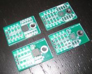
Attached are two PDF files with the board outlines and top/bottom components.
These are all printed to scale, so you can get the exact size by printing them to scale on a standard 8.5 x 11 sheet.
These are the final release boards, so you can feel free to design your chassis and drill holes based on these files!
I'm working through the schematics now, and I will then generate a BOM for each board. These should be done by the end of the week.
Cheers,
Owen
Attachments
Hi Owen,
Is there something you're not telling us about in the bottom left corner or have I missed something? 😀
UHPSR?
Cheers,
Chris
Is there something you're not telling us about in the bottom left corner or have I missed something? 😀
UHPSR?
Cheers,
Chris
Hi Chris,
Good eye! You're close, but that's not it...
I'll give a free mystery board to whomever can guess correctly though, based solely on the outlines given 😉
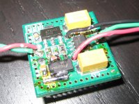
The UHPSR is in final prototype stages, and as you can see in the picture, it's not a pretty board anymore after so many changes, but it performs oh-so-well in its current state 🙂
I can fire you a few prototype boards to play with for fun, but the real deal should be available pretty soon in a prettier format.
The proto board layout is designed to replace the tridents on the BII or BIII and I think the final version will look much the same as what you see in the picture, minus the puddles of flux everywhere. It's good for 1.2V or 3.3V from a 5V supply, and current can be set pretty easily, but maxes out at 200mA.
A word of warning... it's not a cheap shunt reg to put together, but it's well worth it 🙂
Cheers,
Owen
Good eye! You're close, but that's not it...
I'll give a free mystery board to whomever can guess correctly though, based solely on the outlines given 😉
The UHPSR is in final prototype stages, and as you can see in the picture, it's not a pretty board anymore after so many changes, but it performs oh-so-well in its current state 🙂
I can fire you a few prototype boards to play with for fun, but the real deal should be available pretty soon in a prettier format.
The proto board layout is designed to replace the tridents on the BII or BIII and I think the final version will look much the same as what you see in the picture, minus the puddles of flux everywhere. It's good for 1.2V or 3.3V from a 5V supply, and current can be set pretty easily, but maxes out at 200mA.
A word of warning... it's not a cheap shunt reg to put together, but it's well worth it 🙂
Cheers,
Owen
Attachments
49990 plus tant caps ... I can see how that's going to get expensive.
Ohhhh I see what it is now, I see it.
BAL-BAL front end with discrete buffer output stage for use as IV? [addmission: I worked out that I could click on the outlines and get part numbers, OPA1632 was the giveaway 😀]
Cheers,
Chris
Ohhhh I see what it is now, I see it.
BAL-BAL front end with discrete buffer output stage for use as IV? [addmission: I worked out that I could click on the outlines and get part numbers, OPA1632 was the giveaway 😀]
Cheers,
Chris
Last edited:
49990 plus tant caps ... I can see how that's going to get expensive.
Ohhhh I see what it is now, I see it.
BAL-BAL front end with discrete buffer output stage for use as IV? [addmission: I worked out that I could click on the outlines and get part numbers, OPA1632 was the giveaway 😀]
Cheers,
Chris
Hey! I didn't even know you could do that!
You're very close, but you have to think in the opposite direction 😉
As for the shunt reg, it's the LT parts that end up breaking the bank, and the two tantalum caps are replaced with Panasonic polymer parts which are some of my new favorite things.
Did anyone here know that the microphonic noise from large value ceramic caps can actually be a dominant source of noise in a reg with an extremely low noise floor? I found that out the hard way...
Cheers,
Owen
Ohhh that was my next option, but you hadn't mentioned ADCs in a while so I didn't want to bring it up and get people asking 😀. Well... that's even more interesting 😎
Some of the low noise LT voltage reference chip datasheets mention ceramic cap microphonics as a noise source I'm pretty sure. I spent a while reading up on that actually there are a few LT app notes on nV level noise measurements that are pretty interesting. I have in back of my mind that next year I'd like to do a layout for something similar to the thermal RMS noise measurement layout that frek (sp?) has shown on here, though I wasn't sure about LNA for input. I didn't think the 1632 was good for high (40dB) gain though? that's from memory it's been a long while since I've looked that up. So that begs the question, how much gain can we get out of this fancy little ADC front end that you've got cooking? I'm looking for TT input stage for ADC and low noise amp for measurements which in my world may as well be the same circuit because bandwidth of interest (0-100kHz plus or minus a bit) is the same in both cases. Maybe I'm getting a bit ahead of myself by thinking these things though? qusp has a layout for a similar circuit sitting on his computer too but he's been tied up the last few months with family health problems again 🙁
The Panasonic SP caps are very nice indeed, qusp pointed them out when he was using them on his low profile BAL-BAL from memory and he gave me some LT1963 regulator PCBs and I've used some of the SP-caps on there too I think.
Cheers,
Chris
Last edited:
Hi guys, I have been following this and the mian thread of the wire amps, and I'm interested in purchased a few pcb, but I have never participated in a group buys before, could someone please tell me how to do it? thanks. Sorry for my bad english.
Hi cloudalmasai. Go to the first page of this thread, the first link is to the Google Doc spreadsheet for ordering PCB's ... Enter your details & what boards you want, once ready OPC will send out a payment request 🙂
The UHPSR is in final prototype stages, and as you can see in the picture, it's not a pretty board anymore after so many changes, but it performs oh-so-well in its current state 🙂
I can fire you a few prototype boards to play with for fun, but the real deal should be available pretty soon in a prettier format.
The proto board layout is designed to replace the tridents on the BII or BIII and I think the final version will look much the same as what you see in the picture, minus the puddles of flux everywhere. It's good for 1.2V or 3.3V from a 5V supply, and current can be set pretty easily, but maxes out at 200mA.
A word of warning... it's not a cheap shunt reg to put together, but it's well worth it 🙂
Cheers,
Owen
That news made my day.
HQ 1.2v Trident replacement is not that easy to find over here...
Would it be also a good replacement for feeding the 3.8v AVCC of ES9018/ES9012 based dacs ?
Hi cloudalmasai. Go to the first page of this thread, the first link is to the Google Doc spreadsheet for ordering PCB's ... Enter your details & what boards you want, once ready OPC will send out a payment request 🙂
Ok, thanks. Order place,
rsavas pretty much hit the nail on the head... it's because of the TO-220-7 pack availability for the TPS7A3301.
Even with a hot plate, a microscope, solder paste and a fine point iron, I struggle to solder the QFN pack for the TPS7A4700. If you want to actually dissipate any power, you need to tie the power pad to a large ground plane, or better yet a heatsink. Soldering the power pad correctly basically necessitates a hot air setup, or an oven with a stencil.
I think people have a hard enough time soldering 0805 parts, and on a scale of 1 to 10 for difficulty, I would rate the QFN as a 9 and an 0805 as a 1 or 2.
Although I would have loved to use the 4700, I ended up using the 3301 so people could mount the TO-220 pack the standard way, bend the leads, and solder it just like a LM317/337.
Cheers,
Owen
Forgot to come back and mention this ... I did solder a TPS7A4700 reg of iancanada's design by hand without hotplate or hot air. You're right Owen, it is a challenge. Ian even accidentally connected a Tant cap in reverse and light it on fire. Certainly not my-first-smd-work sort of stuff but depending on the size of the copper plane it might be doable by hand. I have a few more of his boards here that I was thinking to use in a few other places but haven't got to those projects yet. He used a hole to get to the power pad but I have no real way of knowing exactly how well I flowed that solder other than to feed a bunch in the hole and hope ...
The other difference is that the TPS7A4700 won't go below 1.4V, from memory the TPS7A3301 will go a touch lower, though it's rare that we want to go that low it's a limitation in some applications.
Cheers,
Chris
That news made my day.
HQ 1.2v Trident replacement is not that easy to find over here...
Would it be also a good replacement for feeding the 3.8v AVCC of ES9018/ES9012 based dacs ?
Indeed, this is what they were really designed for. I'm running mine at 3.5V for AVCC, but I think they should be good for 3.8V. You may want to bump the input supply up to 5.5V if you go that high, but it will probably work as-is.
Forgot to come back and mention this ... I did solder a TPS7A4700 reg of iancanada's design by hand without hotplate or hot air. You're right Owen, it is a challenge. Ian even accidentally connected a Tant cap in reverse and light it on fire. Certainly not my-first-smd-work sort of stuff but depending on the size of the copper plane it might be doable by hand. I have a few more of his boards here that I was thinking to use in a few other places but haven't got to those projects yet. He used a hole to get to the power pad but I have no real way of knowing exactly how well I flowed that solder other than to feed a bunch in the hole and hope ...
The other difference is that the TPS7A4700 won't go below 1.4V, from memory the TPS7A3301 will go a touch lower, though it's rare that we want to go that low it's a limitation in some applications.
Cheers,
Chris
It is certainly possible to solder them by hand, but it is very high on the difficulty scale, especially the power pad. To get good dissipation to the back plane, you really should be using 5 to 9 smaller vias, which makes soldering tricky.
My original plan was to have a run of TO-247 size regulator daughterboards built up, and provide these along with the PSU to allow people to use to TPS7A4700. These boards were designed to bolt up to a heatsink just like a TO-247 pack, and the power pad is brought back to the rear ground plane to allow for good dissipation. I use these for prototyping, but decided that buying all the regs and having a panel built wasn't the best path forward. It would have dramatically increased the cost of the PSU, and if people really want the 4700 regulators, they can always look into the finished products I'm working on 🙂
As for the mystery board, you went a little too far in the opposite direction.
It's a low voltage DC coupled NTD1. It uses the NTD1 as an I/V converter, but with lower gain and much lower resistor values which allows the current to stay high (150mA) with reduced voltage rails. It's also makes the common mode DC voltage at the output low enough to feed directly into a OPA1632 which makes up for the lower voltage gain of the NTD1 by applying some additional voltage gain. This circuit allows the I/V to do what it does best, and the op-amp to do what it does best, all while keeping power dissipation in check. It simulates beautifully, but we'll see how it makes out in the real world next week! I know people have been anxious to get rid of the coupling caps, and this is one way to do it.
Cheers,
Owen
Attachments
NTD1?
Lost me on this one!
Owen,
Can you not make the center via a bit bigger and solder the power pad from the backside allowing the solder to wick through to the top side power pad? This of course assumes that the top is solder first.
I used a MAX9729 in a 5x5x0.8mm TQFN and did by hand. I ruined the first part, you can not let the soldering iron tip touch the package or it will ( I assume) De-laminate the part and damage it. Had to buy a Sparkfun hot air machine to remove the part.
Hardest part is getting the initial alignment and the first pad soldered. This is where a HASL finished pcb can be an advantage. I also found out that I should have opened up the solder mask, on the perimeter, to allow the solder iron tip to contact the exit trace(fan-out) from the pad and conduct heat (solder to flow) through/along the trace/land to the pkg pad. Seems to be enough flux in the glow core solder so I did not need extra flux.
So in my case for the second go at it, I scrapped off the solder mask a bit to allow for this. Looks like you have this figured out, if I zoom in on your pad, looks to me that you left enough room to get the iron tip on the pcb land area.
Fun wow!! Keep up the great products.
Rick
Lost me on this one!
Owen,
Can you not make the center via a bit bigger and solder the power pad from the backside allowing the solder to wick through to the top side power pad? This of course assumes that the top is solder first.
I used a MAX9729 in a 5x5x0.8mm TQFN and did by hand. I ruined the first part, you can not let the soldering iron tip touch the package or it will ( I assume) De-laminate the part and damage it. Had to buy a Sparkfun hot air machine to remove the part.
Hardest part is getting the initial alignment and the first pad soldered. This is where a HASL finished pcb can be an advantage. I also found out that I should have opened up the solder mask, on the perimeter, to allow the solder iron tip to contact the exit trace(fan-out) from the pad and conduct heat (solder to flow) through/along the trace/land to the pkg pad. Seems to be enough flux in the glow core solder so I did not need extra flux.
So in my case for the second go at it, I scrapped off the solder mask a bit to allow for this. Looks like you have this figured out, if I zoom in on your pad, looks to me that you left enough room to get the iron tip on the pcb land area.
Fun wow!! Keep up the great products.
Thx for the heads up, this applies to what sizes/ranges? what dielectric types(X7R,COG/NPO)?Did anyone here know that the microphonic noise from large value ceramic caps can actually be a dominant source of noise in a reg with an extremely low noise floor? I found that out the hard way...
I remember when I worked for HP, we were only allowed to use fused tanatalums, from Kemet, for this very reason.Ian even accidentally connected a Tant cap in reverse and light it on fire.
Rick
Last edited:
I've looked through the relevant threads bit haven't found and answer to what FETs may be used for the LME48930 boards. What are the recommended output transistors (as I seem to recall ACD101NDD and ACD103PDD are no longer available)?
Somewhere buried Owen has a list.
I bought TT Electronics/Semelab's/Alfet
These guys have so many names, I do not know why.
These are available from Newark/
ALF16N16W ALF16N20W
ALF16P16W ALF16P20W
I also have these #'s
Exicon ecw20n20-z.
Exicon ecw20p20-z
A link for you
MOSFETs | Newark element14 Canada
Mine came from Farnell in the UK
The dual-die Semelab parts are the ones to use.
ALF16N20W:
ALF16N20W - SEMELAB - MOSFET,AUDIO,N CH,200V,16A,TO | Farnell United Kingdom
ALF16P20W:
ALF16P20W - SEMELAB - MOSFET,AUDIO,P CH,200V,16A,TO | Farnell United Kingdom
I have 10 complimentary pairs left over from the first GB of them, so if anyone is interested then please start a list in this thread. Add your diyAudio name and quantity required. I think they were $20 a set and based on the current pricing, that's roughly half price.
I also have a pile of 160V N channel parts (ALF16N16W) that would be perfect for anyone looking to build with less than +/- 70V rails. I will let these go for $5 each. All you'd need to do is grab the equivalent P channel parts:
ALF16P16W - SEMELAB - MOSFET, P CH, -160V, -16A, TO | Newark
Cheers,
Owen
- Home
- Vendor's Bazaar
- "The Wire" Official Boards for All Projects Available Here! BAL-BAL, SE-SE, LPUHP