The TPA3110D2PHP (PowerPad) & TPA3110D2RGZ have a thermal pad that is to be pasted to a thermal plane/vias for heat transfer to inner/outer layers to act as the device heat sink!! The DS shows this info on pages 37-40I have a TI TPA3100D2 board running 8 ohm speakers from a laptop supply and it barely gets warm with music at the edge of clipping. It has no heat sink at all and makes about 15 WPC
TPA3118/30 do the same, but with a different package(HTSSOP-DAP). TPA3116, due to its extra power/heat, needs an external HS, thus the pad up version(HTSSOP-DAD).
The TPA3100 is a QFP and it does have a pad in the center of the package that uses the PC board for a heat sink. There is no external heat sink on either side. The chip gets quite warm if driven hard with sine waves into a load resistor, but remains near room temp if driven to the edge of clipping with bass heavy music.
I would recommend DIY those with thermal on top.
Just saying its hard to inspect undeneath without
an xray... Adequate electrical connection to GND
does not mean you got good thermal connection.
Just saying its hard to inspect undeneath without
an xray... Adequate electrical connection to GND
does not mean you got good thermal connection.
Oop's. I guess I should get the part number correct to begin with
TPA3100D2
I have to admit that I did not paste/solder/reflow the thermal pad on bottom of the TPA3100D2 for the 2 pcb's prototypes that I designed and then hand soldered up. I realized after the fact, that I could have made a much larger center via and allow the solder iron to heat up the backside pad/via and flow solder onto the thermal pad on the component side. The footprint as document by TI in the spec is geared for reflow soldering process with solder paste screening, which is the usual production solder process for this part.
I agree that the pad up version (HTSSOP-DAD) as used on TPA3116 is the best for the DIY community. To bad it was not released when I designed with the TPA3100D2. None the less the TPA3100D2 barely get's hot even driving 4 ohm speakers with a audio source. Continuous sine wave testing at full power, is certainly another matter.
Bridge Tied Load, means no speaker connection to circuit ground
In the data sheet page 18
MONO MODE (PBTL)
The TPA31xxD2 family can be connected in MONO mode enabling up to 100W output power. This is done by:
• Connect INPL and INNL directly to Ground (without capacitors) this sets the device in Mono mode during
power up.
• Connect OUTPR and OUTNR together for the positive speaker terminal and OUTNL and OUTPL together for
the negative terminal
• Analog input signal is applied to INPR and INNR
Add to that,
4 RINP I Positive audio input for right channel. Biased at 3 V.
5 RINN I Negative audio input for right channel. Biased at 3 V.
10 LINP I Positive audio input for left channel. Biased at 3 V. Connect to GND for PBTL mode.
11 LINN I Negative audio input for left channel. Biased at 3 V. Connect to GND for PBTL mode.
circuit drawn on page 14, fig 27, showing the sub connections.
Its all in the data sheet and eval pcb's, just have know English and a bit about electronics.🙂
Acronym Definition; PBTL: Pacific Bangladesh Telecom Ltd. PBTL: Probabilistic Branching Time Logic (distributed computing) PBTL: Project-Based Teaching and Learning
Parallel Bridge-Tied Load (PBTL). One single-channel from using all of the amplifiers in a parallel bridge-tied load configuration for the highest power possible.
Last edited:
Hi, Alright guys, come down to earth and speak in English. If the 3116 is BTL and we need to PBTL (whatever that is) to get more power. Speak English please and tell us how to do it.😀
Look at page 14 of data sheet:
http://www.ti.com/lit/ds/symlink/tpa3116d2.pdf
3116 is two BTL but can be configured to PBLT to drive a 2R load.
You get higher power by having a lower load resistance. The PBLT mode increases output current capability to drive said load.
Last edited:
Hi, Alright guys, come down to earth and speak in English.
I tried plain English in post # 484
The 3116 can operate in Parallel Bridge Tied Load mode (PBTL in the data sheet). Here the two BTL channels are wired in parallel, which allows 2 ohm operation.
Speak English please and tell us how to do it
TI drew us a picture.
Look at page 14 of data sheet:
There are two 3116 chips in that schematic.
The top chip is configured in normal BTL (Bridge Tied Load) mode producing two channels of 50 watts each into 4 ohm loads.
The bottom chip is configured for PBTL and produces one channel of 100 watts into a 2 ohm load.
The two (different) Chinese boards that I have ordered have two chips on each board with one stereo BTL and the other mono PBTL for the subwoofer.
I would recommend DIY those with thermal on top.....Adequate electrical connection to GND does not mean you got good thermal connection.
I have been hand soldering these types of packages in my day job for years (RF power amp chips). If you have professionally made PC boards with plated through holes that are large enough you can apply enough heat and solder paste from the back side to reflow the chip. We usually solder a copper heat spreader on to the back side too.
You can use one or two strands of thin wire from a line cord through the holes on a home made pc board on a QFP chip like the 3100, since you can still solder down the leads individually if the chip isn't perfectly flat. This doesn't work too well on a QFN.
I will be making my own board, so that's why I chose the 3116 even though I don't need 200 watts. It would seem that the 3116 and the 3118 have the same die inside, while the 3130 has smaller output devices.
Great, post a pic of it, I'd like to take a look.I will be making my own board,
Look like the 3116 chip based amp has attracted a lot more attention than I thought 😉
I finally got my Aliexpress 3116 amp running last night (had been working on my bath room for the last month). Glada to hear what I heard and that 17$ was well spent. The base was tight and low, mid range is full. A very minor criticism is the lightly elevated level of sibilance (maybe it was the recording). Everything was very pleasant.
I am going to let it play for a while before trying all those mode that you guys have mentioned.
That 3 pin adaptor at the input was a pain in the butt to remove. I was trying to look for a connector for it but could not find any.
Regards,
Look like the 3116 chip based amp has attracted a lot more attention than I thought 😉
I finally got my Aliexpress 3116 amp running last night (had been working on my bath room for the last month). Glada to hear what I heard and that 17$ was well spent. The base was tight and low, mid range is full. A very minor criticism is the lightly elevated level of sibilance (maybe it was the recording). Everything was very pleasant.
I am going to let it play for a while before trying all those mode that you guys have mentioned.
That 3 pin adaptor at the input was a pain in the butt to remove. I was trying to look for a connector for it but could not find any.
Regards,
WAs this the connector you were looking for?Yuan Jing Audio - ON SALE! - Stereo RCA Inter-connection Board - $1.28 - Connectors
John
Looking on the YG website, now there's a six channel version: Yuan Jing Audio - ON SALE! - TPA3116 Class-D 6.0 Channels Stereo Amplifier [50W x 6] - $32.64
These been getting popular, huh? Good choice for 5.1 setups or three-way active speakers.
A wiki-style info source would be good, and before the thread becomes too big.
These been getting popular, huh? Good choice for 5.1 setups or three-way active speakers.
A wiki-style info source would be good, and before the thread becomes too big.
WAs this the connector you were looking for?Yuan Jing Audio - ON SALE! - Stereo RCA Inter-connection Board - $1.28 - Connectors
John
Yes!!! I should have asked around earlier. I cannot understand why YJ did not use those ubiquitous terminal block, like those they put on the board for speaker connections?
Regards,
Well the T amp is back in the system. The obliteration of my Fine Arts Radio frequency reception has forced me to temporarily abandon the little D class amp.
Has anyone tried to shield or otherwise contain the fm problem?
Has anyone tried to shield or otherwise contain the fm problem?
If you do do not want to give up on FM then dump the D amp. I have purchased 5 inexpensive D amps and they all ruin FM reception.Well the T amp is back in the system. The obliteration of my Fine Arts Radio frequency reception has forced me to temporarily abandon the little D class amp.
Has anyone tried to shield or otherwise contain the fm problem?
Google, "D amp FM interference", lots of problems.
I'm at present using a $6 tda7297, sound great and FM is unspoiled
http://www.diyaudio.com/forums/class-d/231988-what-heck-its-less-than-lunch.html
If you want extra power another chip amp I have is a tda7294, also very good.
Yup, thanks for the confirmation. It's so weird that it will only affect a particular freq. (91.5 MHz) and as far as I can tell not much else on the fm band.If you do do not want to give up on FM then dump the D amp. I have purchased 5 inexpensive D amps and they all ruin FM reception.
Google, "D amp FM interference", lots of problems.
I'm at present using a $6 tda7297, sound great and FM is unspoiled
http://www.diyaudio.com/forums/class-d/231988-what-heck-its-less-than-lunch.html
If you want extra power another chip amp I have is a tda7294, also very good.
I will try a Ti Shield surrounding for the D . The Ti Shield is two layers of copper with stuff (?) sandwiched in between.
My T amp is a Trends 10.1 with all the mods Audiomagus had so it is rather refined sounding.
So, thanks. I had seen your other posts but no success resolving this.
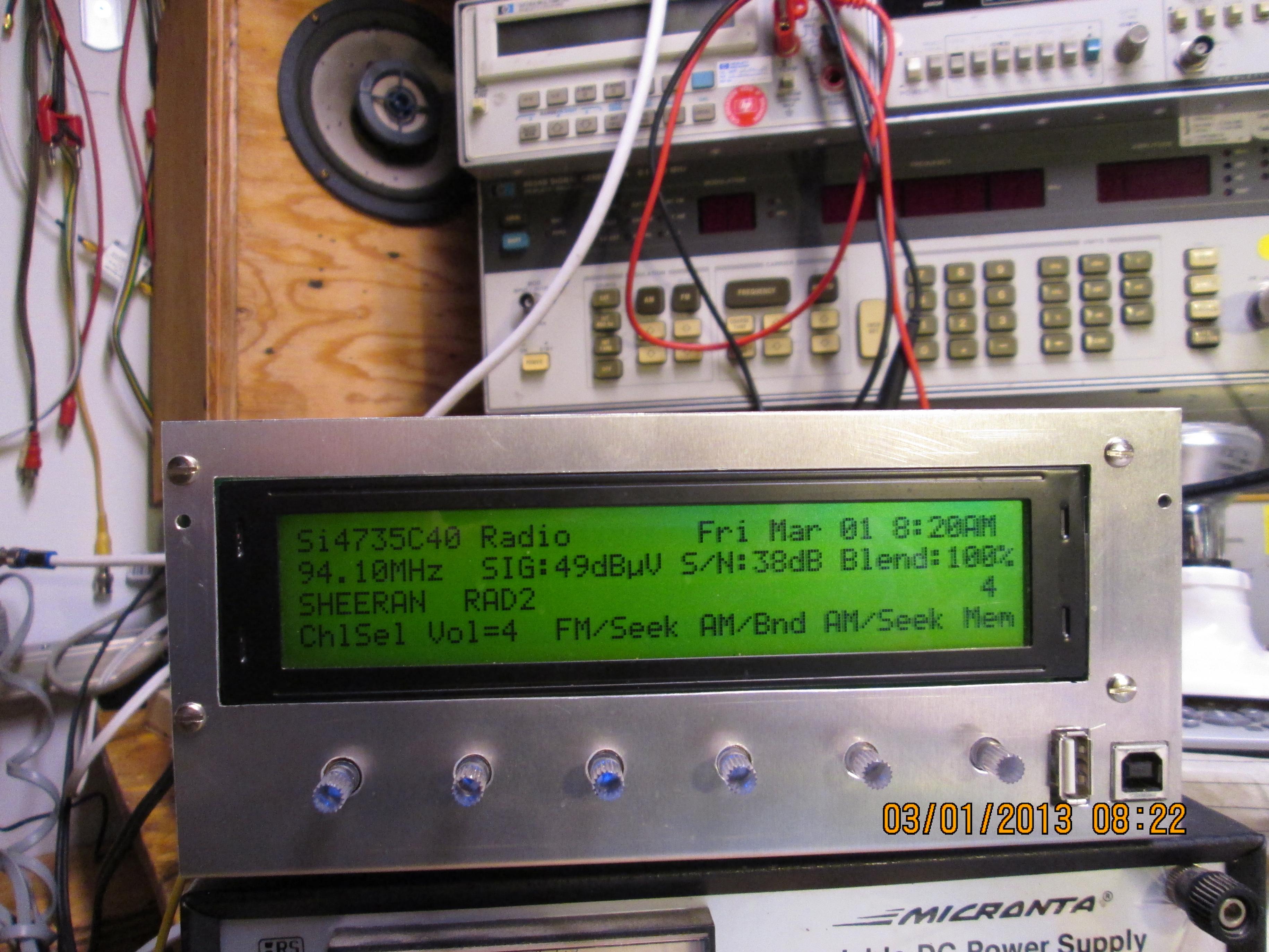
Rsavas built a very nice all-in-one CPU controlled FM/MP3 receiver with a TPA3100 and did not report that interference was a problem. http://www.diyaudio.com/forums/class-d/219730-tpa3118d2-4.html#post3392283
Wether it is because of the area I live in, perhaps I need a roof antenna? With either the tda7297 or tda7294 I get no rf interference.
I get the feeling that the Chinese builders read diyaudio and quickly introduce amps that have been modded as per the group?
My first D amp, a Lepai 2020 was noisy with FM but hopeless with a SMSL SA-SA that had air coil inductors, which according to the group was a "great improvement".
My first tpa3116 was also poor with fm and the updated "deluxe version" with huge toroidal inductors was a disaster. A tpa3123 was also noisy.
I have tried ferrite beads, a mains isolating transformer, switching and traditional psu with no luck.
I have long speaker leads, my 2 speakers are designed to fit the corners of the room.
I have read that very short speaker leads are required for D amps to avoid picking up rf interference, so the problem could be here?
Im not climbing on the roof or putting my speakers together.
Interesting reports.
To get any respectable fringe/distant FM reception, an antenna on a tower with amp on top is necessary.
I have a deep fringe log-periodic mounted around 40' feet up with an amp and 300 ohm twin lead to another distribution amp in the basement.
Shielded coils are imperative, if you ever want to meet FCC, other wise you have a radiator that is not contained.
Having a good solid muti-layer ground planes obviously help's too.
There are a lot of details to make a solid design, just not as simple as copying a data sheet.
I do not have an issue with speaker leads, mine are probably 6 feet long, with no shielding/twisting, although I initially thought that I would need to shield the speaker cables as well.
I have done FCC testing before, out in the country(Halton Hills), far away from strong radiators, ie. CN Tower. Had to build our own Ethernet cables to pass. Stock cables could not contain the RF as they cheaped out and did not have double shielding.
To get any respectable fringe/distant FM reception, an antenna on a tower with amp on top is necessary.
I have a deep fringe log-periodic mounted around 40' feet up with an amp and 300 ohm twin lead to another distribution amp in the basement.
Shielded coils are imperative, if you ever want to meet FCC, other wise you have a radiator that is not contained.
Having a good solid muti-layer ground planes obviously help's too.
There are a lot of details to make a solid design, just not as simple as copying a data sheet.
I do not have an issue with speaker leads, mine are probably 6 feet long, with no shielding/twisting, although I initially thought that I would need to shield the speaker cables as well.
I think that it is more a case of radiating rather than picking up rf interference.I have read that very short speaker leads are required for D amps to avoid picking up rf interference,
I have done FCC testing before, out in the country(Halton Hills), far away from strong radiators, ie. CN Tower. Had to build our own Ethernet cables to pass. Stock cables could not contain the RF as they cheaped out and did not have double shielding.
Shielded inductors as Rsavas pointed out should really make a big difference. Encasing the amp inside a metal shielding box that is grounded and separate from the FM board will help too. But simple use of class A/B amp, if that sounds good to you is an acceptable solution. The class D is more power efficient so for someone using solar power and batteries may be necessary.
You know what is noisy? Bluetooth transceiver units - they have residual buzz and noise that is a pain to get rid of.
You know what is noisy? Bluetooth transceiver units - they have residual buzz and noise that is a pain to get rid of.
Switching Amplifier (Class D) Basics | Audioholics
D amps are perhaps more problematic than most modders care to admit to, read passage on inductors. The writer is, I gather, well qualified.
I'm a music lover with neither the patience or experience to trouble shoot these inexpensive amp. The little chip amps perform flawlessly for me, but for the tweekers there is not much to work with ;-)
- Home
- Amplifiers
- Class D
- TPA3116D2 Amp