1. nothing prevents you from trying , even if final issue can be slightly different top end response , comparing to use of plain repeater
Thank you for the quick response. It encourages me to go ahead.
One thing still bothers me about using higher impedance transformer is that I read somewhere about the gate leakage current of SS Jfets. I am not sure whether it applies to R100 too, but as I remember, someone suggested to drive SS Jfets with lower impedance sources than Mosfets to prevent unstable operation.
Anyway, the only way to fild out is to try. I will let you know what happens.
Thank you.
Last edited:
considering cost of , primarily, rest of hardware ( PSU , heatsinks/case) , ordering a apir of Jensens isn't arm & leg
so , play with what you have , and order Jensens , sparing LLs for something more suitable for them
so , play with what you have , and order Jensens , sparing LLs for something more suitable for them
Buzzin' da Buzz
ook me , beat me ...... I can't remember (again) and I can't find your post about custom x-fillar xformers you got ........
so , please - enlighten me - is it 5 or 6-fillar ...... and where is that post
(or just write basic info again - who made it and for how mucho greenies )
TIA
ook me , beat me ...... I can't remember (again) and I can't find your post about custom x-fillar xformers you got ........
so , please - enlighten me - is it 5 or 6-fillar ...... and where is that post
(or just write basic info again - who made it and for how mucho greenies )
TIA
proper arrangement of 6-fillar , to have that funny toob looking feedback , as in original
thd spectra looks scary - only third , 80db bellow
I mean - scary , even if crude sim
How does this compare with just bridging to F6 amps, possibly modifying the feedback networks to conform to your design? Circuit-wise, the main difference is two quad-filar transformers instead of one hex-filar trafo.
somehow , I fancy more option with one core
part from tech reasons , part from strictly romantic 😉
part from tech reasons , part from strictly romantic 😉
One thing still bothers me about using higher impedance transformer is that I read somewhere about the gate leakage current of SS Jfets. I am not sure whether it applies to R100 too, but as I remember, someone suggested to drive SS Jfets with lower impedance sources than Mosfets to prevent unstable operation.
Thank you.
In the context of gate leakage current applied to a SemiSouth SiC JFET biased into Class A, then an R100 will have forward gate leakage current of about the same amount as the likely alternatives such as the R100A or R125. This is because the gate leakage current is caused by forward biasing the gate-source pn junction above the threshold voltage which is positive for an enhancement mode JFET (Vt = 0.75-1.25 V from datasheet). Positive threshold voltage is one of the little miracles that SemiSouth brought to JFETs, but you can't fool Mother Nature hence the need to provide a trickle current into the gate when Vgs is at its typical bias of between 1.5-1.75 V.
When you mention transformer "impedance" in this context I assume you are referring to the real-part of the impedance, meaning the winding resistance. If so, then your concern is potentially valid, but it depends on the other resistances in series with the gate which can easily dominate a transformer's winding resistance. Like if a potentiometer is used for adjustable bias.
Good luck!
ook me , beat me ...... I can't remember (again) and I can't find your post about custom x-fillar xformers you got ........
so , please - enlighten me - is it 5 or 6-fillar ...... and where is that post
(or just write basic info again - who made it and for how mucho greenies )
TIA
Cinemag 5 filar.
I will probably request a 6 filar(more versatile,IMO), but it will be some time. Immmersed in other activities at the moment. Not sure, but BudP seemed to ellude to the fact that with each additional winding, there is potential for degradation of performance.
One thing still bothers me about using higher impedance transformer is that I read somewhere about the gate leakage current of SS Jfets. I am not sure whether it applies to R100 too, but as I remember, someone suggested to drive SS Jfets with lower impedance sources than Mosfets to prevent unstable operation.
The only issues I have encountered are at DC, where in some circuits (for
reasons of simplicity) you wish to bias the Jfet through a high value resistor
so as to have a high input impedance. In that case, Gate leakage becomes
part of the DC equation, and is typically a factor above 10 Kohm so so.
Transformers actually alleviate this, as their DC impedance is usually 100
ohms or less, but their AC impedance can be high.
In either case, it takes pathologically high leakage figures to create
problems for these audio circuits, and I cull any such cases out in testing
as being defective parts.
😎
tnx Buzz
hopefully , I'll not forget it this time
let me know when you , whenever , try 6-fillar
damn ..... I just remember that I have somewhere some nice toroid nickelsomethingamorphous cores ........ gonnna threw them to winder guy ......
damndamn - I just realize , again , that I simply have no use even for smallest balanced F6 like amp ........
You can always use two quad transformers, keeping one common winding
from each for operation in series or parallel. This gives you 2 inputs and
six outputs.
😎
from each for operation in series or parallel. This gives you 2 inputs and
six outputs.
😎
I know that ...... made xformer microphone stereo matrix maybe even before I knew how to solder properly (well , with my Guru above my head , using Bolex telescope as teaching device 😛 )
but , where's the challenge then ....... certainly not mixed with simplicity
but , where's the challenge then ....... certainly not mixed with simplicity
The major difference of using two quad transformers vs. one hex transformer will be the interwinding capacitance effects. In a balanced design you will still get even order harmonic cancellation, but I do not know about how the odd order harmonics compare in these two situations.You can always use two quad transformers, keeping one common winding
from each for operation in series or parallel. This gives you 2 inputs and
six outputs.
😎
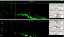
here it is , even if both crude sims (no capacitances in xformer models) , it's probably usable as comparison
will try later with some nF here and there 😉
edit : enclosed what I have as Funny^F6 ;
tried with added parallel capacitance in data for each winding , 470p arbitrary
THD spectra looking practically the same
too late at night to play with sweep
it's indicative that Funny is having neg third .....
and - food for thought(s) for tomorrow - arranging two quad-filars to have same funny toob looking NFB , as in origigi F6 ....
Attachments
Last edited:
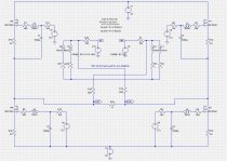
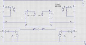
last one before going to sleep - I realized that I made it (sim) , 6 months ago - Funny^F6 , with proper NFB arrangement .......
here is the result (pics )
whatever - main difference between 2 x quad-filar and one 6-filar ....... seems phase difference between origin and third
here is the result (pics )
whatever - main difference between 2 x quad-filar and one 6-filar ....... seems phase difference between origin and third
Attachments
Last edited:
here it is , even if both crude sims (no capacitances in xformer models) , it's probably usable as comparison
will try later with some nF here and there 😉
edit : enclosed what I have as Funny^F6 ;
tried with added parallel capacitance in data for each winding , 470p arbitrary
THD spectra looking practically the same
too late at night to play with sweep
it's indicative that Funny is having neg third .....
and - food for thought(s) for tomorrow - arranging two quad-filars to have same funny toob looking NFB , as in origigi F6 ....
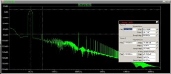
Something looks wrong with the bottom (maybe both) THD spectrum. I have seen this before in circuits with capacitors. You need to run the simulation for a period of time before capturing data for the FFT, otherwise the caps have not stabilized. The causes the FFT noise floor to have the ramping effect from low to high frequencies. I see 20dB to 40dB reductions in the noise floor by adding a delay.
yup , I didn't include that then (working on/from old files ) but - what I'm interested in is relatively clean - I'm not looking much above , say , 5KHz and only for gross peaks/dips
though , different thing when simulating for freq sweep
anyway , tnx for noticing - always beneficial to share tricks'n'tips
though , different thing when simulating for freq sweep
anyway , tnx for noticing - always beneficial to share tricks'n'tips
The only issues I have encountered are at DC, where in some circuits (for
reasons of simplicity) you wish to bias the Jfet through a high value resistor
so as to have a high input impedance. In that case, Gate leakage becomes
part of the DC equation, and is typically a factor above 10 Kohm so so.
Transformers actually alleviate this, as their DC impedance is usually 100
ohms or less, but their AC impedance can be high.
In either case, it takes pathologically high leakage figures to create
problems for these audio circuits, and I cull any such cases out in testing
as being defective parts.
😎
Hi Nelson,
Thank you for the clear instructions.
Can I interpret that, in F6 circuit, gate leakage issue depends on the sum of DC resistance P1, R5, R7 and winding resistance? If so, for high gate leakage parts, lower R5 will help?
I wish I could sort out high gate leakage parts as defective, but it is almost impossible for me to get extra R100s.
Thank you.
In the context of gate leakage current applied to a SemiSouth SiC JFET biased into Class A, then an R100 will have forward gate leakage current of about the same amount as the likely alternatives such as the R100A or R125. This is because the gate leakage current is caused by forward biasing the gate-source pn junction above the threshold voltage which is positive for an enhancement mode JFET (Vt = 0.75-1.25 V from datasheet). Positive threshold voltage is one of the little miracles that SemiSouth brought to JFETs, but you can't fool Mother Nature hence the need to provide a trickle current into the gate when Vgs is at its typical bias of between 1.5-1.75 V.
When you mention transformer "impedance" in this context I assume you are referring to the real-part of the impedance, meaning the winding resistance. If so, then your concern is potentially valid, but it depends on the other resistances in series with the gate which can easily dominate a transformer's winding resistance. Like if a potentiometer is used for adjustable bias.
Good luck!
Hi Semisouthfan,
Thank you for sharing your knowledge on Sic Jfet. Also, you are right I was meaning 'winding resistance' when I was saying 'transformer impedance'.
I have quickly wired F6 up with lundahl LL1690 which has 150ohm resistance in each windings. It takes about 1.5v Vgs for 1.5A bias and is stable so far for a couple of hours now. Does it mean those Jfets have acceptable gate leakage current? Or does it take a while before I can be sure?
Thank you.
- Home
- Amplifiers
- Pass Labs
- F6 Amplifier