Hi,
Pics and schematic of the line stage section at
VNAV • View topic - KSL-M77 Preamplifier by KONDO, Audio Note Japan.
If I understand the schematic, and assuming that the schematic is correct, the first tube runs at 140Vp-k at ~500uA per section and about the same for the DC coupled CF. Pd ~0.07W - tubes would last a long time!
Looks kind of standard and un-inspiring, yet so highly reviewed even at 30k or so (with phono).
In house caps and resistors, a 6X4 in parallel with SS diodes, some electro B supply caps. I might have to build this thing.. can it be THAT easy?
Shane
Looks like a standard "constant current", output buffered gain stage, designed "by the book" values taken from the spec sheet design examples.
Don't see why not, just don't try to drive long runs of cable with it,as there isn't much current sourcing capability there.
Don't see why not, just don't try to drive long runs of cable with it,as there isn't much current sourcing capability there.
Looks kind of standard and un-inspiring, yet so highly reviewed even at 30k or so (with phono).
There is simply no point building this without Kondo parts, chasis, wire and general magic. "Un-inspiring" is a very mild way of putting it.
There is simply no point building this without Kondo parts, chasis, wire and general magic. "Un-inspiring" is a very mild way of putting it.
Points well taken, and reminds me of the Ongaku article back in SP mag. ie. dont bother unless xyz.
Twenty years later there are some pretty good caps available in the small values required and tantalum and/or old stock carbon comps cant be 'that bad'.
Theres no silver wound iron required. A couple inches of silver or enamelled copper wire, copper chassis, hybrid rectifier and.. it might sound different, but you'd think it'd not necessarily be worse. ??..
Like you say, un-inspiring, and I agree - Looks like the stock version of the $99 bottlehead foreplay lineamp from 10 years ago with a different tube.
Question is: how to turn a sows ear into a silk purse?.. hocus pocus cant be the answer. The operating points are all there.
Is it just me?. (dont answer that part) 🙂
Shane
The purpose of such a design, even when executed with the designated parts is a mystery to me. I just don't think it can provide "modern" sound. Romantic and lush? Definitely. Stunning dynamics, solid state rivaling bass, instant transients? Hardly.
The combination of tube selection, standard cathode follower and low working currents just do not do what i want. Prejudiced? Certainly 🙂
The combination of tube selection, standard cathode follower and low working currents just do not do what i want. Prejudiced? Certainly 🙂
People will pay 30k for that?! Please tell me the chassis has thick gold plating, so you are paying for the metal.
And thats all I can put it down to.. its generating something different than usual with the low currents.. and 500uA is about 20% of where the 6072A is usually set up.
I did hear the line section of this unit in Singapore in conjunction with some really good gear, and it altogether it was better than anything I'd heard before, but who knows.
Gonna try it anyway.. see how it works out as a DAC output stage, get rid of the input cap and use a I/V resistor for 'grid leak'. See how it stacks up against hybrid mu follower 6072A, 6922 and D3A as triode.
At least I'll know then.
As for the price, well.. I guess its like membership to a club. No gold, but copper runs about $8k per tonne 🙂
Where do you see the PSU schematic? I heard that they use only a couple RC filtering cells after 6X4 rectifier (no SS diodes) and first cap into 6x4 is 100uf. Owners are changing rectifier tube every few months . I wonder why ;?)
Phono section gets choke filter. Sometimes you have to wonder why thay make that choices. Disgruntled former Kondo dealer on Audio Asylum shares distributor price list and $32k retail M7 preamp cost dealers ONLY $6900 . He commented that he sold Ongaku for $28k and still made a profit. I heard Kondo is only such a "hopla" brand abroad thanks to Peter Qvortrup marketing aforts. In Japan it doesn't have that much recognition, prestige and it's a lot cheaper. Not sure if they sell much in Japan.
PS . That dynamic tube sound rivaling solid state it's an Audio Research signature -somehow nobody makes clones ..
Last edited:
In the pic at the linked site you can see the SS diodes across the 6X4. Also, google search confirms.
100uf after 6X4 may not be so critical with such low current demands, even if it was used without the SS bypass. There was some comments about the M7 5687 version about this floating around a couple years back.
Kind of odd that they need to replace the 6X4, you could pull it completely and the stage would still function 🙂
Cant comment on the markup, or PQ. I noticed EIFL put 20% or so on all their export transformer prices. Give it a few years and if you're not holding USD, you could probably pick one up quite reasonably with a currency exchange from one of the more solid currencies. Japan debt vs GDP is off the charts. House of cards and second healthiest horse in the glue factory 🙂
Agree with Audio Research, but I think the comment in context referred to solid state bass reproduction.
Best to you,
Shane
You right , I see it now. For a moment I thought that SS rectifiers are in series but they look to bypass 6x4 .
I went and got a KSL-M77 kit without the transformer or caps. And for that matter, the case too and various other parts.
I started looking for a transformer today with the following specs:
INPUT = 117va
OUTPUT #1 = 500VCT/250.0.250
OUTPUT #2 = 12.6VAC
I found that finding a transformer with these specs is nigh unto impossible. Its the 12.6V filament winding.
So I got to thinking. Why do they want 12.6V? The 12AY7's. And why are the 12AY7s even in he circuit? WAYYY too much gain for what we got going on here.
Then I thought some more and came to conclusion that replacing ALL of the 12AY7s with 12AU7s may be just the thing to do.
Advantages:
1) The circuit is not going to have to put up with a ridiculous amount of gain.
2) The filament winding on the power transformer can be 6.3V
3) in eliminating the 12.6V filament supply, much of the noise is eliminated too, and
4) the transformer will be much easier found.
But what will need to be altered to accommodate the 12AU7's? Someone was saying that the inly real required change would be to putt all of the 5K1 resistors in the cathode circuits.
Here is where I need some help... I need to know exactly what needs to be done to the circuit to make all of the 12AU7's happy and feel right at home.
Thank you!
....................Why do they want 12.6V? The 12AY7's.....
12AY7 will run either 6V or 12V. Just like 12AU7, or T, or X.
Here they want the 12V connection because they use DC on the heaters and higher voltage lower current suits available parts much better.
The phono section DOES want a hi-gain tube. Even 12AX7 is not always enough for accurate bass EQ.
Attachments
Last edited:
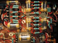
Regarding all of the resistors in parallel - are they for creating the correct resistance as the circuit intends..
or
Are they for the support of different types of tubes? Perhaps the circuit as shown is for 12AY7s but if one were to not include the 5K1 resistors, those sockets could take 12AU7s?
Also does anyone know the exact Marantz circuit this preamp was copied from?
Thank you,
or
Are they for the support of different types of tubes? Perhaps the circuit as shown is for 12AY7s but if one were to not include the 5K1 resistors, those sockets could take 12AU7s?
Also does anyone know the exact Marantz circuit this preamp was copied from?
Thank you,
Do you have a link that refers to the kondo in question ? The aboveHi,
Pics and schematic of the line stage section at
VNAV • View topic - KSL-M77 Preamplifier by KONDO, Audio Note Japan.
If I understand the schematic, and assuming that the schematic is correct, the first tube runs at 140Vp-k at ~500uA per section and about the same for the DC coupled CF. Pd ~0.07W - tubes would last a long time!
Looks kind of standard and un-inspiring, yet so highly reviewed even at 30k or so (with phono).
In house caps and resistors, a 6X4 in parallel with SS diodes, some electro B supply caps. I might have to build this thing.. can it be THAT easy?
Shane
link goes to a vietnam forum.
This is the highest resolution schematic I have found to date:
A link to it may also be found 3 entries previous.
https://www.diyaudio.com/forums/attachments/tubes-valves/902912d1608351939-kondo-m77-ksl-m77-42-gif
A link to it may also be found 3 entries previous.
https://www.diyaudio.com/forums/attachments/tubes-valves/902912d1608351939-kondo-m77-ksl-m77-42-gif
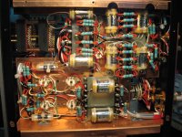
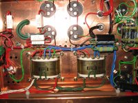
I found these images archived from the web-address in Viet Nam.
Resistor values in the circuit traced schematic appear match the photographs.
Note SS diode bypasses across the 6X4 rectifier.
Resistor values in the circuit traced schematic appear match the photographs.
Note SS diode bypasses across the 6X4 rectifier.
Attachments

Last edited:
Sadly the pic isn't informative enough, but those SS diodes might also be part of a hybrid Graetz bridge rectifier. What should a SS diode bypass be good for?
Best regards!
Best regards!
- Home
- Amplifiers
- Tubes / Valves
- Kondo M77