I dreamed Pass Aleph 0s and recently acquired it in the end.
It's now 19 years old, but I wants to keep maintaining it for another decades.
To do that, I searched service manual of Aleph 0s, replacement components, etc. I studied many threads in this forum, too.
As a result, I get more confident to maintain my lovely Aleph 0s with replacing components in time. My major is electrical engineering and I am familiar with analog circuits, soldering, using equipments (voltage/current meter, oscilloscope, function generators.).
My first maintenance is to replace power capacitors.
I have read several threads about how to select the capacitors;
Per this forum, recommended one is
Rifa PEH169 ir PEH200, 47,000uF, 63V, +/-20%, -40~85C, 28.5mm screw space
(with bypass film capacitor is recommended, too.)
To assess the physical efforts of the task, I opened my Aleph and was stuck at mechanical parts.
"How to efficiently (minimally) disassemble & assemble it to replace the caps?"
I don't want to fully disassemble it and think there will be best-cut for the replacement task.
Dears, could you advise?
Attachments
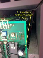
first cut those white wire bridges (later replace them with new ones )
rest is self-explanatory
(use solder-sucker for cleaning old solder , to have free solder-holes for new bridges)
use both camera (meaning - plenty of pics during disassembly) and red/black marker to mark position/orientation of important things ( pcb , caps)
rest is self-explanatory
(use solder-sucker for cleaning old solder , to have free solder-holes for new bridges)
use both camera (meaning - plenty of pics during disassembly) and red/black marker to mark position/orientation of important things ( pcb , caps)
Before you cut the wire bridges, un-screw the finned heatsink from the U-channel. There should only be the screws holding the 2 parts together, as the output transistors mount to the U-channel.
The original Aleph chassis was very easy to open up and access - I suggest you open it up a bit further and see if you can access the capacitor bank.
The original Aleph chassis was very easy to open up and access - I suggest you open it up a bit further and see if you can access the capacitor bank.
Dear Zen Mod,
Thanks for your advice.
I didn't expect "to cut" internal wires to replace the caps.
Then, I cannot help asking another question to you;
What's your recommendation for Jumper wire?
I am considering 22AWG single-core either silver wire or copper wire.
Is 22AWG reasonable?
Which one is recommended, silver or copper, (or combination?)
U-channel means ...
Dear 6L6,
Thanks for your advice.
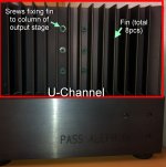
To clarify the term of "U-Channel and fin," I attached the picture.
Is my illustration correct?
Then, if I release 6 screws x 4 sides, 8 pieces of fins are disassembled and core of U-Channel (4 colums of 8xIRF244 output stage + PCB + 4 power caps) will be revealed.
Do I correctly guess?
Dear 6L6,
Thanks for your advice.
To clarify the term of "U-Channel and fin," I attached the picture.
Is my illustration correct?
Then, if I release 6 screws x 4 sides, 8 pieces of fins are disassembled and core of U-Channel (4 colums of 8xIRF244 output stage + PCB + 4 power caps) will be revealed.
Do I correctly guess?
Attachments
My upgraded cap is
CAPACITOR, 47000UF, 63V, 65X105
Product Range: EVOX RIFA - PEH200 Series
Capacitance: 47000µF
Capacitance Tolerance: ± 20%
Voltage Rating: 63V
Diameter: 65mm
External Length / Height: 105mm
Lead Spacing: 28.5mm
ESR: 0.01ohm
Life Time @ Temperature: 60000 hours @ 85°C
Capacitor Terminals: Radial Leaded
Operating Temperature Range: -40°C to +85°C
By my rough measurement, this cap can fit into the chassis.
(I guess the height is a little smaller than the original cap.)

cheapskate Papa
so , how then to replace them (wires) with some of well known audiophool quality ?

- no need for dismantling outputs assembly from heatsink ....... only in case that visual/tactile inspection reveal that thermal goo is dry/better to replace from whatever reason
so , how then to replace them (wires) with some of well known audiophool quality ?
- no need for dismantling outputs assembly from heatsink ....... only in case that visual/tactile inspection reveal that thermal goo is dry/better to replace from whatever reason
Dear 6L6,
Thanks for your advice.
To clarify the term of "U-Channel and fin," I attached the picture.
Is my illustration correct?
Then, if I release 6 screws x 4 sides, 8 pieces of fins are disassembled and core of U-Channel (4 colums of 8xIRF244 output stage + PCB + 4 power caps) will be revealed.
Do I correctly guess?
Yes, you are correct~
I did release those screws a few months ago but hesitate to disassemble my Aleph 3.
Because I can't figure out how to start disassembling them.
I have an Aleph 3 (have owned and enjoyed more than 18yrs) which I've found some hizz and little hum recently.
A signal for dry out capacitors? or dysfunction xformer?
Any idea?
Last edited:
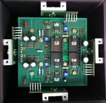
The U-channels would be the 4x unanodized aluminum you see on your top view pic. These 4 run the total height of the heatsinks and hold the TO-3 power mosfets. These U-channels also hold the heatsinks upright with the black Allen bolts you see on the sides.
I would guess the 8x big flathead screws on the top view pic connect and mount the 4 power supply capacitors onto the circuit board. Two each diagonally per cap.
I would guess the 8x big flathead screws on the top view pic connect and mount the 4 power supply capacitors onto the circuit board. Two each diagonally per cap.
Even though student (me) should be self-motivated to learn by himself as much as possible, many advices are big help for him. Thanks, everybody.
In summary, my action plan is
0. To prepare good thermal paste as well as replacement components.
1. To open one-side of fins and peep at what structure is with my own eyes
2. Depending on structure, to determine to replace all of electrolytic caps (6x 200uF,50V & 2x 4.7uF, 100V)
3. If possible, I will try "not to cut" wires at first. Pull out solid wires with soldering tip.
4. If cutting wire is really needed, I refer to following summary (from Soundhappy, thanks)
**2**
Audio signal path |
very tight diameter
materials |
solid core copper,
silver plated cooper
(in this case some silver adds in solder)
isolated |
teflon,cotton,shielded be a nice option
care |
same lengh,menage neat
example |
screened wire from Belden UTP cable
***3***
Solder |
60/40 sn | pb
its for diyers with who care to don't move components in solder process
63/37 sn | pb| rosin core |
easy better for preventing cold joints
care | keep clean from oxides contacts before soldering...
it be solid in time and have better conductivity
example | brands Ersin,RS,Jaycar,Kester,Fluitin
high quality for industry standard
==
5. To record the progress and post the report in this thread
== Replacement caps
31000uF -> Rifa 47000uF
220uF, 4.7uF -> Elna Simic II
BTW, can someone send me service manual of Aleph 0s?
I googled it but its links are obsolete.
I obtained Aleph 0 service manual and refer to it to guess Aleph 0s.
Some cap values of 0s are different from those of 0.
I googled it but its links are obsolete.
I obtained Aleph 0 service manual and refer to it to guess Aleph 0s.
Some cap values of 0s are different from those of 0.
Even though student (me) should be self-motivated to learn by himself as much as possible, many advices are big help for him. Thanks, everybody.
In summary, my action plan is
0. To prepare good thermal paste as well as replacement components.
1. To open one-side of fins and peep at what structure is with my own eyes
2. Depending on structure, to determine to replace all of electrolytic caps (6x 200uF,50V & 2x 4.7uF, 100V)
3. If possible, I will try "not to cut" wires at first. Pull out solid wires with soldering tip.
4. If cutting wire is really needed, I refer to following summary (from Soundhappy, thanks)
**2**
Audio signal path |
very tight diameter
materials |
solid core copper,
silver plated cooper
(in this case some silver adds in solder)
isolated |
teflon,cotton,shielded be a nice option
care |
same lengh,menage neat
example |
screened wire from Belden UTP cable
***3***
Solder |
60/40 sn | pb
its for diyers with who care to don't move components in solder process
63/37 sn | pb| rosin core |
easy better for preventing cold joints
care | keep clean from oxides contacts before soldering...
it be solid in time and have better conductivity
example | brands Ersin,RS,Jaycar,Kester,Fluitin
high quality for industry standard
==
5. To record the progress and post the report in this thread
== Replacement caps
31000uF -> Rifa 47000uF
220uF, 4.7uF -> Elna Simic II
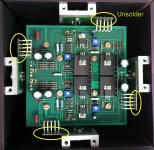
Albert, It is not neccessary to cut the wires.
Please refer to the following photos.
After a close inspection, the wires can be de-soldered.
Refer to the photo 1, after desolder the wires from the PSU board,
the PCB can be un-screwed and removed from the chasis.
However, I am not sure how to un-screw the bolt at the centre of the PSU board. (see photo 2)
Attachments
Inside Aleph 0s (U-channel)
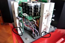
Thanks, B&W_Arthur. Aleph 0s is structure is different from yours as attached pictures.
With releasing 2 fins, I can understand the simple structure of upper part of Aleph 0s.
To replace power caps, the sequence is
1. Remove all 8 fins (unscrew total 24)
2. Remove hood (it should follow Step 1 to hold mechanical support on columns at Step 1)
3. Pull out (unsoldering, not cutting) 4 x 5 lines between PCB and output stages
4. Release 4 x 2 screws of power caps
5. Release power cap clips (it should follow Step 4 to hold mechanical support at Step 4)
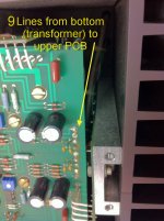
6. Lift the PCB. At this step, you don't need to unsolder upper 9 power lines & lower 3 power lines from bottom part. The lines are extra long to give some free lift distance.
7. Replace caps one-by-one
8. To check whether there is mistake of short or not.
9. Reverse steps from 6 downto 1.
BTW, there is no mark of thermal paste between fins and columns. Anyway, I'll apply thermal paste (very thin) at interfacing surface among them.
Thanks, B&W_Arthur. Aleph 0s is structure is different from yours as attached pictures.
With releasing 2 fins, I can understand the simple structure of upper part of Aleph 0s.
To replace power caps, the sequence is
1. Remove all 8 fins (unscrew total 24)
2. Remove hood (it should follow Step 1 to hold mechanical support on columns at Step 1)
3. Pull out (unsoldering, not cutting) 4 x 5 lines between PCB and output stages
4. Release 4 x 2 screws of power caps
5. Release power cap clips (it should follow Step 4 to hold mechanical support at Step 4)
6. Lift the PCB. At this step, you don't need to unsolder upper 9 power lines & lower 3 power lines from bottom part. The lines are extra long to give some free lift distance.
7. Replace caps one-by-one
8. To check whether there is mistake of short or not.
9. Reverse steps from 6 downto 1.
BTW, there is no mark of thermal paste between fins and columns. Anyway, I'll apply thermal paste (very thin) at interfacing surface among them.
Attachments

Last edited:
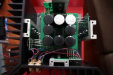
To replace whole electrolytic caps on PCB
There are 6 x 220uF (50V, 105C) and 2 x 4.7uF (100V, 85C) electrolytic caps on PCB.
To replace them, unsolder lower 3 power lines and then, the PCB can be flipped bottom-up.
I have not decided to replace them at this moment since I want to feel incremental changes of sound. 1. Power Caps -> 2. Other Caps
A. What's your recommendation? To replace them at once or not.
And I have question on the specification.
B. 220uF 50V, 105C: Is there specific reason of 105C? I think 85C will work and then, ELNA simic2 (only upto 85C) can be selected as replacement.
C. 4.7uF 100V, 85C: Is there specific reason of 100V? I think 50V will work and then, ELNA simic2 (only upto 50V) can be selected as replacement.
I don't want to say Silmics weren't up to this, but consider it's extremely hot inside the Aleph 0
as it's class A and it's poorly vented. 105° types are more reliable in this environment. I'd go for
105° LL caps wherever applicable.
I even have some 125° Sikorels located pretty close to the amp pcb/heatsink.
as it's class A and it's poorly vented. 105° types are more reliable in this environment. I'd go for
105° LL caps wherever applicable.
I even have some 125° Sikorels located pretty close to the amp pcb/heatsink.
I found additional 4 x 4.7uF 100V, 85C at output stage columns.
Reason of 105C is persuasive. It's trade-off between lifetime and "guessed-to-be-better" component.
How about 4.7uF 100V?
BTW, I am leaning to replace all of them at once, since 1) iteration of thermal shock on PCB hole patterns to pull/put wires is minimized 2) iteration of mechanical weariness of screw lines of aluminum chassis (disassemble/assemble) is minimized 3) my fatigue is reduced 🙂
Last edited:
Consider voltage, temperature rating, capacity and physical size first, then "sonic" reputation.
Most reputable manufacturers (like BC, BHC, Elna, Epcos, Fischer & Tausche, Krummer, Nichicon,
Panasonic, Sanyo etc.) also make 105°/125° rated lytics, many of them regarded as great sounding.
Most reputable manufacturers (like BC, BHC, Elna, Epcos, Fischer & Tausche, Krummer, Nichicon,
Panasonic, Sanyo etc.) also make 105°/125° rated lytics, many of them regarded as great sounding.
- Status
- Not open for further replies.
- Home
- Amplifiers
- Pass Labs
- Pass Aleph 0s: How to disassemble & assemble it to replace power capacitors?