I have no probs soldering SMD, but if the general consensus is people want TH, then that's what we do . . . nothing stopping us doing 2 layouts either.
This is only a buffer my friends . . .
🙂
This is only a buffer my friends . . .
🙂
I know you dont bonsai, my post is not a reflection on your design, just a reminder to those with their heads in the sand. soon enough all the stuff with any leads at all will start to disappear, its already getting a bit thin on the ground
Last edited:
soon enough all the stuff with any leads at all will start to disappear, its already getting a bit thin on the ground
That's why I am stocking parts already!
If I have only one precious pcb, I dislike the idea to experiment with it by first time SMD soldering. I could try with something that I won't regret if I ruin, may be some cheap SMD kit. Of course that I fear to ruin very good pcb by soldering SMD components. Also, I am 50, my sight is not as it used to be and sometimes soldering TH parts could be drag if the pads are too close, let alone SMD.
If the name of the site is diy(something) it means that it is (mostly) for amateurs, not for pros. Sometimes I visit EETimes and other pro sites, but 99% of us here are amateurs.
Last edited:
Ivan,
The funny thing is even on the professional sites I am on the same arguments go on there! A bit more educated but still there are differing personalities arguing the same points or just finer distinctions of disagreement.
The funny thing is even on the professional sites I am on the same arguments go on there! A bit more educated but still there are differing personalities arguing the same points or just finer distinctions of disagreement.
This is what I had in mind. Pcb can have additional holes for chassis mounting, and two sets of holes for both RK27 and RK16 (=standard) pots. If pcb pot is not desired one can solder pcb pins instead and connect pot with pcb using shielded or unshielded cables. Maximum flexibility!
Attachments

That would have to be SMD! I am working on the TH version now (middle circuit) and there's quite a lot of stuff on the board. Lets see how this goes, and then I'll start a second SMD version which will be all out compact.
I know you dont bonsai, my post is not a reflection on your design, just a reminder to those with their heads in the sand. soon enough all the stuff with any leads at all will start to disappear, its already getting a bit thin on the ground
Yes, I agree - leaded comps are on their way out - no option in the long run but to go with the flow.
I have a range from +1/4 to +3.5 and three different magnifiers.
But best of all is good lighting.
But best of all is good lighting.
I am using +0,5 now but when prescribing them to me doc said: "You shall come for a new pair in one year." and that was 3 years ago! This pair is absolutely inadequate for SMD work.
No we don't. I am looking forward to getting my "Subbu V3 DAC", and I would be surprised to find any TO-92's in the BOM there. I also do not plan on experimenting with it, it is pretty much a complete product.It's very easy to transform this simple project into diyer's nightmare by two simple steps:
1. use hard to obtain expensive parts from many different sources
2. use miniature SMD parts that many diyers find difficult to solder
We do not want to compete with Nagra Kudelski in miniaturization game, don't we?
Hiding one's head in the sand (or silicon) has nothing to do with it.
I do not think that potential users should have to jump through any hoops for a manual volume control with a unity buffer, whose main purpose is to attenuate a line level signal, so it can be amplified again in another circuit six inches away.
Small size is not a factor, because it will be installed inside a chassis which is a minimum 4 inches (10 cm) deep, and probably close to 6 inches (15 cm). It's closest neighbor will probably be a transformer which weighs in at 5-7 lbs. It simply has to fit behind the front panel, that is the only constraint.
The challenge is not designing the most technically elegant circuit with exotic components. I can already buy or build one of those, for less than what I have spent on Starbucks while reading some of those threads... 😉 Tying the design to surface mount components, or to unique components makes it attractive to fewer people.
edit:
If it does have to be small for other people, I am open to using an opamp and a couple 3-pin regulators.
Last edited:
Is it wise to force yourself to use SMD parts that are so obviously meant to be assembled by automated machines and not by humans? Of course, humans can do it too, with great effort, but is it worth it? SMD parts are small so that industry can make them cheaper not because they are better. It is well known that the same opamp sounds better in metal cans version than in DIP case. And by analogy ....
I am travelling around china this week on business. I'll only be able to work on the buffer next w/end.
Is it wise to force yourself to use SMD parts that are so obviously meant to be assembled by automated machines and not by humans? Of course, humans can do it too, with great effort, but is it worth it? SMD parts are small so that industry can make them cheaper not because they are better. It is well known that the same opamp sounds better in metal cans version than in DIP case. And by analogy ....
complete nonsense, well known nonsense, but still nonsense. its 'well known' that all tubes sound warm and lush, while solid state sounds clinical. does that make it true? its all about application, if you can hear any difference at all at less than -140dB… (performance of the best opamps, whether soic8, or to99) lets say i'd be somewhat surprised.
seriously,its pretty clear you are now just talking about stuff youve never even attempted. time to solder sot23 jfet : 1 second, looking at one side of the board. pick it up with tweezers, place it on the board, solder it, done. time to solder to92 jfet, probably around 5-10 seconds, since you need to insert, then flip the board over, maybe youve even had had to prep the leads, then you need to trim the leads.
but its so much easier… not.
its the same for resistors, or caps, no need to prep/bend the leads, no need to trim the leads, things get in your way less often too.
the parts we are talking about here are dead easy to work with, no need for a machine, I am not a robot, I use it out of preference, not just for performance. then of course if you need to do oarts that dont have any leads, or more than a few boards, build a reflow oven for less than $120 and solder the whole thing at once; several boards at once.
but I repeat, this board and these parts, far quicker to build SMD, by hand, as a non cyborg human.
youve got all these reasons youve been collecting, sorry but nothing so far holds water.
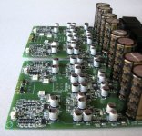
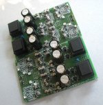
this was one of the first SMD builds I ever did, about 5 years ago (one of the first more involved diy audio builds I did fullstop). its a little bit messy, but once I got into the swing of it, no problem. I did this with an el-cheapo hakko clone and the stock tip
its a Sjorstrom Audio headphone amp, yes I bridged 2 of them for even more overkill. each amp has 4 discrete diamond buffers and 4 Jung type super regulators
you just need to practice and get yourself an illuminated magnifier
Attachments

Last edited:
Bonsai: sorry for the detour, i'll leave it here, I really dont know why people get so stubborn about this topic
@Ivan: No point in you or me doing this by hand, been there, done that, no point of pride in how many parts you can place by hand in an hour, right?
I am glad to have the input from Jean-Paul, Calvin, Qusp, etc... (thanks for taking the time guys!)
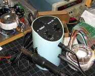
I will go along with whatever you and/or Andrew decide about selection of parts. If you and I and a couple other "adults" need a board or two, as long as the boards pass through my hands, I can populate them w. a few parts using an old hot-air rework station (see below at left).
Just pulled it out of storage last night to see if it still works. It is a bit ancient, like all of my SMD-related stuff, and has not seen the light of day in a while, but it is ok for a few parts. If not, one of the techs who used to work for me can populate a panel faster than I finish a latte, and (unlike me) she can see in stereo and does not make mistakes... 🙄
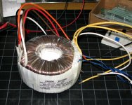
If the power supply voltages become an issue, I plan to use one of the transformers (pic on the right) I bought on ebay almost for scrap prices, which have multiple secondary windings. Gross overkill, but cheaper than what I use for our other joint project.
To anyone else: consider my objections retracted, I always reserve the right to change my mind about anything audio... 😀
I am glad to have the input from Jean-Paul, Calvin, Qusp, etc... (thanks for taking the time guys!)
I will go along with whatever you and/or Andrew decide about selection of parts. If you and I and a couple other "adults" need a board or two, as long as the boards pass through my hands, I can populate them w. a few parts using an old hot-air rework station (see below at left).
Just pulled it out of storage last night to see if it still works. It is a bit ancient, like all of my SMD-related stuff, and has not seen the light of day in a while, but it is ok for a few parts. If not, one of the techs who used to work for me can populate a panel faster than I finish a latte, and (unlike me) she can see in stereo and does not make mistakes... 🙄
If the power supply voltages become an issue, I plan to use one of the transformers (pic on the right) I bought on ebay almost for scrap prices, which have multiple secondary windings. Gross overkill, but cheaper than what I use for our other joint project.
To anyone else: consider my objections retracted, I always reserve the right to change my mind about anything audio... 😀
Attachments
Last edited:
I didnt say what I said about speed as a point of pride, just that it was presented as something more difficult somehow, when with practice, the will and/or the right tools, its the opposite. pin spacing of sot23 vs to92 really isnt even very different.
we all have our humanity that catches up with us, I wouldnt attempt to do the boards above without magnification these days I dont think. hot air and sot232/323 might be a bit of an issue, depends how adjustable the flow is, but indeed very handy things; you can pick up a cheap one on ebay for ~$50 these days
I wish you all luck regardless. I just see a lot of people on this forum resisting this so very strongly and I dont really get it, the parts will continue to shrink, better get to terms with that.
It was used for rework in small quantity, one part at a time, so yes, the tips have to be swapped for different parts, and hot air temp set. You would not want to reflow a panel this way. Yes, they show up on ebay often, like most old Weller equipment....hot air and sot232/323 might be a bit of an issue...
I think that for the group buy we should use "big" pcbs with all TH parts so that "standard" diy-ers (old folks) can do it. We should provide another "ultra compact" all-SMD option with pcb files for "advanced" builders and let them organize their own production of pcbs because this version will be less attractive for the majority of builders.
- Status
- Not open for further replies.
- Home
- Source & Line
- Analog Line Level
- Bonsai's practical buffer