only for a continuous stream of sinewaves.The voltage and current are 90 degrees out of phase remember.
At the moment before closing the switch both V & I into the transformer are zero. At the moment after the switch is closed V & I are non zero. There is no 90degree phase lead/lag.When Vi is at max, current is passing through zero. So, switch on at Vmax is not a bad idea at all.
... Eva demonstrated it about 6 or 7 years ago with what I thought was a truly inspired and simple circuit...
I was able to find the thread. Unfortunately many of the links are now out of date and the schematics have vanished.
Uses power resistors, so not quite what I plan, but is purely TRIAC based and claimed to be noiseless even with no shunt relay.
There was some discussion around the idea of phase control to eliminate the resistive limiter but not reduced to practice as far as I could see.
So still plausible but unconfirmed.
Thanks for the clue. Any more information about prior art always appreciated.
Best wishes
David.
I have a big grinder.
The ON/OFF trigger works through some control circuit that slowly brings the grinder up to operating speed.
Takes about 1/4s to just start turning and a further 1s to reach full speed.
During this time the semis must be warming up. But I suspect the "variable resistance" is in circuit for such a short time that heating is not a big issue. I should probably open it up and find out how small a heatsink they have fitted !
This idea seems to have started from Rod Elliot's website. He is usually very informative but I think this one is incorrect.
The idea seems to be that an inductor driven by a sine wave potential has the peak current when the sine wave potential crosses zero.
This is true only of the steady state condition and does not apply to the initial transient solution.
This is classic maths that you can check but the intuitive explanation is simple.
When the source is connected at the time the potential is zero then there is obviously no current flow. As the potential increases the current will then increase. Toni's link supports the idea, as far as my Deutsche can tell.
One complication is if the transformer core was left partially magnetized because the power was cut under load. The transformer may draw increased current if the remnant field is in the reverse direction to the reconnection.
I have never seen data on this. I should be able to calculate the approximate size of the effect but it depends on the core material.
This was one of my questions. Anyone have data or calculations on this?
Self claims the inductive component is usually more than the power supply capacitor inrush but provides no data and it doesn't look correct to me.
Cordell's picture on p355 shows the capacitor load clearly and the inductive inrush is not evident, but it may be off scale, so still not proof.
Best wishes
David
David,
I strongly suggest that you do some further reading, and/or do a physical experiment yourself. The simple answer is that I am right (and by definition, you are not).
Worst case inrush current for the inductive part of a transformer occurs when the mains is switched on at zero-crossing. This has been verified experimentally and there is an oscilloscope capture that proves it (see Inrush Current. There are also many credible websites that will verify that this is the case.
For minimum (inductive) inrush current, the mains should be switched on at the peak of the mains waveform. When a transformer is followed by a large capacitor bank, there is no optimum point to switch because there are two conflicting requirements to minimise inrush current.
You have made a classic and understandable error in your analysis, and I suggest that you improve your knowledge before making statements that will mislead others.
Worst case inrush current for the inductive part of a transformer occurs when the mains is switched on at zero-crossing.
Hi Rod
As I pointed out previously I think the problem mainly is miscommunication.
The peak inductive inrush current does not "occur when the mains is switched on at zero"
Subject to assumptions about the remnant field
It occurs a half cycle after the mains is switched on but if it is switched on at zero.
I think this is what you meant?
For minimum (inductive) inrush current, the mains should be switched on at the peak of the mains waveform.
This is where the previously mentioned assumptions about remnant field kick in.
Karl (Mooly) linked a decent paper that showed the effect pretty clearly.
Michael Konstanzer discusses this at the EMEKO site too.
Says it's a useful rule of thumb for some transformers but not necessarily for toroids.
I am inclined to believe him, his product looks to be used in bio-medical equipment and they are a bit stricter on tests than DIY audio.😉
When a transformer is followed by a large capacitor bank, there is no optimum point to switch because there are two conflicting requirements to minimise inrush current.
A phase switched system looks like it could resolve this conflict.
Found a previous thread where someone actually built this.
Says it was extensively tested and worked well but some of his results don't quite make sense to me. Want to study this more. I would be interested in your opinion.Link for phase controlled soft start
Best wishes
David
BTW. Thanks for the informative website.
Last edited:
That's an ESP article I have not read for a long time. Lot's of new material added. Updated Aug 2013.
I will need to read in detail.
As I noted in my earlier post, understanding the behavior of the BH loop is key - perhaps a bald 'switch on at Vpk because current lag by 90 degrees' is not accurate. Nevertheless, you do NOT switch on at the voltage zero crossing. Look at the EMEKO paper page 4. The mains is applied as a succession of pulses at 130 degree phase angle until B and H are established and then the full mains cycle is applied. It's clear that the BH loop starts small (area) and is then expanded over a number of cycles to the full loop area ( see fig 2 RHS image).
In the earlier link I posted, the recommendation was to apply mains at 70 degrees after the voltage crossing. As the author of that paper noted, quite some investigation went into establishing the optimum firing angle to prevent problems.
Clearly turning off to ensure remanence is removed is also key to a successful implementation.
This has the makings of a very interesting project and a chance to popularize an underutilized technique.
Hi Rod
As I pointed out previously I think the problem mainly is miscommunication.
The peak inductive inrush current does not "occur when the mains is switched on at zero" (etc.)
Dave,
You seem to have assumed that the word 'when' implies 'at the exact moment', but this is not the normal meaning of the word. It is quite obvious that no current flows if there is zero voltage, but the first half cycle is effectively a large DC 'event' and the transformer winding reacts by saturating the core.
As you can see from the 'scope capture in my article, all subsequent current pulses are unidirectional - effectively DC. This continues until normal operation takes over after the core is demagnetised - typically around 10 cycles. The effect is far worse with a toroidal transformer because of the lower winding resistance and tighter magnetic coupling within the core.
Your initial post where you claimed I was wrong didn't get into the semantics of the word 'when'. You asserted that zero-crossing switching would result in lower transformer inrush current. This is clearly incorrect.
There is no requirement that there be any remnant field in the core - that just makes the situation slightly better or worse depending on the polarity of remnant flux and that of the polarity of the first half-cycle.
Zero-voltage switching will always cause a high transformer inrush.
This is why a resistive inrush limiter is so effective, because it tames both transformer and filter capacitor inrush currents. The ideal inrush limiter is a Variac, allowing you to slowly increase the AC voltage over a period of a few seconds. You can completely eliminate transformer and capacitive inrush, but this is bulky and expensive and is only suitable for workshop use.
I tried a few years ago to switch a 1 kVA torroid on using a triac and an MCU at the zero crossing and it was a disaster: buzzed, popped triacs, fuses etc. I spoke to our triac guru at work and he told me then that I had to switch on at Vpk, but also pointed out all the other issues like snubbering and remanence. I was a coward and went for resistive in-rush limiting.
I tried a few years ago to switch a 1 kVA torroid on using a triac and an MCU at the zero crossing and it was a disaster: buzzed, popped triacs, fuses etc. I spoke to our triac guru at work and he told me then that I had to switch on at Vpk, but also pointed out all the other issues like snubbering and remanence. I was a coward and went for resistive in-rush limiting.
Not surprised the zero cross didn't work.
Did you check the thread I linked where the TRIAC was phase switched on slowly?
OP said initially had problems as phase increased past half way.
So he ramped it up slowly to half a radian then went directly to full on.
Quicker too.
I'm off to the library to check a few phase control circuits.
I don't know MCUs, sounds like a project for you.😉
Best wishes
David
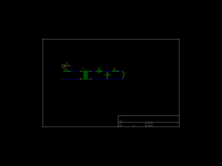
What about using the main reservoir caps as delay-caps?
The primary resistor in my circuit should be relatively large, say 1k, and the secondary res trimmed to turn on the relay when reservoir caps reach some 90% charge. The primary resistor should probably be of the type that is guaranteed to act as a fuse when overloaded.
The primary resistor in my circuit should be relatively large, say 1k, and the secondary res trimmed to turn on the relay when reservoir caps reach some 90% charge. The primary resistor should probably be of the type that is guaranteed to act as a fuse when overloaded.
Attachments
What about using the main reservoir caps as delay-caps?
The primary resistor in my circuit should be relatively large, say 1k, and the secondary res trimmed to turn on the relay when reservoir caps reach some 90% charge. The primary resistor should probably be of the type that is guaranteed to act as a fuse when overloaded.
Something like that would certainly work.
I suspect in practice that the delay needed is very small, perhaps only a few cycles in which case the rise time of "normal rails" and the inherent relay pull in time might be sufficient on its own.
Hi,
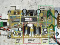
I did a researched and a lots of time trying to prevent the inrush current when turning on any equipment using a transformer. After a lots of trying and error finally I was able to control the inrush current using a micro with not problem. The problem with the inrush current depend only at what time at the AC cycle the transformer it is turned ON or OFF. This will make the transformer to retain a residual magnetization depending at what cycle of the AC it is done. It can be positive or negative. This will make the core to have a residual magnetization of that polarity. Now if you turn ON the transformer at a different cycle that was turn OFF then you will experiencing the inrush current. To prevent this you must repeat you must turned ON/OFF the transformer always at the zero crossing. This will minimizes the residual magnetization of the core of the transformer.
Using this in mind I was able to built a running prototype and it is running on my LM3886 amplifier with a toroidal transformer at least for about 8 months.
The way I am doing it is by when turning ON the amplifier slowly ramp the AC up at the zero crossing and do the same thing at the turning OFF. This will left the transformer core with the smallest residual magnetization.
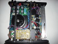
Attached it is a picture of the control board and another with the board mounted in the LM3886 amplifier.
Please read my thread were I explained how to prevent it.
Search for : Preventing the inrush current saturation in a toroidal/EI transformer
I did a researched and a lots of time trying to prevent the inrush current when turning on any equipment using a transformer. After a lots of trying and error finally I was able to control the inrush current using a micro with not problem. The problem with the inrush current depend only at what time at the AC cycle the transformer it is turned ON or OFF. This will make the transformer to retain a residual magnetization depending at what cycle of the AC it is done. It can be positive or negative. This will make the core to have a residual magnetization of that polarity. Now if you turn ON the transformer at a different cycle that was turn OFF then you will experiencing the inrush current. To prevent this you must repeat you must turned ON/OFF the transformer always at the zero crossing. This will minimizes the residual magnetization of the core of the transformer.
Using this in mind I was able to built a running prototype and it is running on my LM3886 amplifier with a toroidal transformer at least for about 8 months.
The way I am doing it is by when turning ON the amplifier slowly ramp the AC up at the zero crossing and do the same thing at the turning OFF. This will left the transformer core with the smallest residual magnetization.
Attached it is a picture of the control board and another with the board mounted in the LM3886 amplifier.
Please read my thread were I explained how to prevent it.
Search for : Preventing the inrush current saturation in a toroidal/EI transformer
Attachments
Something like that would certainly work.
I suspect in practice that the delay needed is very small, perhaps only a few cycles in which case the rise time of "normal rails" and the inherent relay pull in time might be sufficient on its own.
I guess that during the initial toroidal inrush the transformer will not charge the caps. I simulated the circuit in ltspice using an ideal transformer using Rp = 1k (primary resistor), 10 mF cap and approx 22 V secondary (230 V primary) the cap were up to 19 V after 0.1 s and peak power in Rp less than 100 W. With Rp = 100R peak power went up to some 500 W.
Just some minimal engineering to be done to turn it into a working circuit, it seems.
Probably as much trial and error as anything, but yes, should be easy to turn into a working design. I'd perhaps still look at a thermistor as the resistive element, partly on the grounds of them being so small. It's not going to get that hot in a few 10's of milliseconds and would be ready for action almost immediately.
tauro0221... nice implementation, I'm impressed.
Interesting thread loaded with valuable ideas. The schematic of the softstart module sold by our diyAudio store is a classic design by jojod818. I built one for sequencing low power many moons ago. I thought this [silly] idea. Use one or more incandescent light bulbs instead of R15, 16, 17, 18 [each 180R 5W in //]. The inrush current rapidly heats up the Tungsten filament raising its resistance which gets shorted after the time delay.
Best regards
Best regards
- Status
- Not open for further replies.
- Home
- Amplifiers
- Solid State
- Soft start. A (new?) idea and a few questions.