Wahab
I don't think you can put plots up like this without talking about the output power and the load. Again, it concerns me when I see harmonics that are flat like that and not declining with frequency.
The level is in dBV and load is 8R .
Actualy harmonics are not that flat it s just that they have
low level and that the higher ones would be burried in the noise
in a real world measurement , in the case of your E amp H2 is at
about -112dB and we can see that H3 is roughly 10dB lower
in the improved circuit but on the original implementation
odd harmonics are of higher level than even ones wich create
the impression of even order cancelation but actualy it is due
to imperfect linearity of the circuit that will create higher order
odd harmonics out of the H3 with feedback re injection.
Once you reduce this H3 you ll also reduce higher order odd harmonics.
The harmonics wont deacrease more rapidly because as frequency
increase there s less NFB to tame them down.
Edit : As you can see you E amp wasnt maxed out in perfs
that can be way better than your CFA , hence why i m critical
of your CFA attention since you have a circuit that has more
potential , and wich i must admit has my preference
topology wise...
Last edited:
I like to keep an open mind . . .
I have a 350 W CFA I am simming and its at 10ppm - at lower powers its single digit ppm and at 1 Watt it's Low PPB.
The e-Amp will go lower with TPC. Something I will look at again in the future, but not for now since I do not see the point in being fixated on distortion.
🙂
I have a 350 W CFA I am simming and its at 10ppm - at lower powers its single digit ppm and at 1 Watt it's Low PPB.
The e-Amp will go lower with TPC. Something I will look at again in the future, but not for now since I do not see the point in being fixated on distortion.
🙂
No. Thats not it.
I introduced another idea.... the preload (1.2K from supply to ground) on the three terminal reg (LM317/337). Why and for what benefits gained?
Thx-RNMarsh
In my opinion the place for those resistor is power supply unit.
BR Damir
You will need a power supply anyway... so, what PS topology would reduce the need for high PSR in the amp circuit?
Thx-RNMarsh
Shunt regulator for preamp http://www.diyaudio.com/forums/solid-state/235695-no-nfb-line-amp-gainwire-mk2-3.html#post3490591 and capacitance multiplier for power amp http://www.diyaudio.com/forums/solid-state/216780-tt-amp-200w-8ohm-701w-2ohm-2.html#post3115503.
BR Damir
I'm still waiting for we agree on studying on sims the various aspects of CFA, comparing-it to an identical topology (and active devices) VFA one, for we understand better all the behavior's differences.
The requisites are, on my opinion:
- It has to be a power amp able to drive 4Ohm loads
- It has to be as simple as possible.
- It has to use modern components with models available.
- It has to be perfectly stable.
- It has to be cheap, or, at least not too expensive.
I continue to think the VSSA schematic is prefect for this for the following reasons:
- It fulfill the previous requisites.
- It exists and be reported by many builders to sound very nice.
- It measure low distortions numbers in real life, with average modern components.
- It is ultra simple, with only six active devices (CSS apart) and cost less than 40 €, caps apart, board included.
The game may consist in:
- Adding two transistors in the input stage, to transform-it in a LTP.
- Replacing the symmetric feedback path to a single one, returning to the - input of the LTP, changing the impedance for both inputs at 10K.
- Tuning the currents and gain of each stage to optimize the VFA results.
Once this done, we could measure all aspects of both of us, then try to get better numbers for both of us, adding whatever we want: CCS, better PSU filters, diamond buffers, Darlington or simple emitter followers, cascodes, whatever we can imagine on each stage to improve the numbers in sim.
At the end, i thnik everything will be said. It will be time to build two exemplars of each, and compare the listening experience in real life, to figure out what those measuring numbers really brings (slew-rate VS Harmonic distortion, IM).
On my point of view, it is not so interesting to work on CFA only. Lot of CFA amps exists and are known to both sound and measure very good. This has not to be demonstrated any more.
At the end of this collaborative work, i believe all of us will have better understanding of both topologies and that this stupid controversy against CFA will be ended forever.
Last edited:
Hi Esperado !
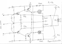
What do you think about this simple fully balanced CFB Amp topology ? ,
with same sex devices everywhere , where precise matching of particular active devices is not big problem at all .
Best Regards !
What do you think about this simple fully balanced CFB Amp topology ? ,
with same sex devices everywhere , where precise matching of particular active devices is not big problem at all .
Best Regards !
Attachments
Last edited:
Just personal feelings.What do you think about this simple fully balanced CFB Amp topology ?
with same sex devices everywhere , where precise matching of particular active devices is not big problem at all .
I always loved bridged amps, and it looks nice (apart the capacitance in the feedback path).
I do not think it would be perfect for the proposed work: A little too exotic, on my opinion, we need CCS in the inputs (for both classical VFA and PSRR rejection) and traditional asymmetric inputs. Also, apart for DC offset, i don't think matching is an option, we have to figure out the evils due to components disparities, and how they behave in both topologies.
As far I'm concerned, if we are in a process where matching active devices is an option, i would go for no global feedback at all. But it would be the matter of an other (interesting) thread. Error correction (or error cancellation) vs NFB. one step more to better understanding of the NFB evils if any.
BTW, The interest to take an existing and proved CFA amp is to save time on the first steps.
Last edited:
Esperado
Thanks for you answer !
Yes this is fully balanced bridge Amp ( Circlotron ) but use CFB not VFB , and of course that can be further evaluated & improved in many other direction using various solution .
BTW ,
PC sound card `M Audio audiophile 192 ` can be very good music signal source for this type of balanced Amps since have fully balanced inputs & outputs .
Last edited:
WOW that looks interesting.
Hi Shaan !
Of course that is interesting ! 😉
Best Regards !
Given two serialised amplifying devices , as in a two stage amplifier ,
it doesnt matter much what topology you are using , assuming it s
correctly implemented there will be no big advantage from a topology
to another linearity wise at first glance.
The difference will appear once you want to improve your design,
then some topologies are easier to enhance to gain more linearity.
The most efficient , obviously , is the discrete implementation
of a uA741 op amp that was popularized by Douglas Self ,
it makes no doubt that the single differential topology
is the one that yield the best complexity/perf ratio.
Following on the list is the symmetrisation of this design,
aka symmetrical differential topology , not as easily implementable.
Last is the usual low impedance inverting input VFAs, wich are wrongly
called CFAs.
Once we look at other parameters than linearity we ll get the same
ranking for all parameters set apart slew rate wich can be more easily
increased with said "CFAs".
Wahab, stop calling CFA's wrongly named. There is a whole industry - and I work in it - that generates hundreds of millions of $ from so called wrongly named CFA's.
Oh, and theres probably been dozens or more like hundreds of PhD grads working on these devices over the last 20 years or so. They are correctly named CFA's and that's what the semiconductor engineering community calls them and they are right. Period.
Oh, and theres probably been dozens or more like hundreds of PhD grads working on these devices over the last 20 years or so. They are correctly named CFA's and that's what the semiconductor engineering community calls them and they are right. Period.
The Blameless is to some people a hugely compromised design:
1. Limited feedback at 20kHz
2. Non symmetrical slew rates
3. Reqiurement for single slope 20 dB/ decade compensation in order to guarantee stability, leading to limited feedback at 20 kHz
4. Non symmetrical PSRR
5. Difficult to get decent slew rates due to tradeoffs between LTP current, input bias current and Cdom
Wahab,
Nobody is obliged to be obsessed with qualities and/or limitations of VFB amps. We want to explore other possibilities. We want to explore what CFB amps can offer and how to achieve max performance from them. That's what this thread is about.
Nobody is obliged to be obsessed with qualities and/or limitations of VFB amps. We want to explore other possibilities. We want to explore what CFB amps can offer and how to achieve max performance from them. That's what this thread is about.
That's exactly why I went out of my way to create an uncompromized "Blameless" variant, though being VFA, coming with its VFA limitations.The Blameless is to some people a hugely compromised design:
1. Limited feedback at 20kHz
2. Non symmetrical slew rates
3. Reqiurement for single slope 20 dB/ decade compensation in order to guarantee stability, leading to limited feedback at 20 kHz
4. Non symmetrical PSRR
5. Difficult to get decent slew rates due to tradeoffs between LTP current, input bias current and Cdom
Hi Esperado !
What do you think about this simple fully balanced CFB Amp topology ? ,
with same sex devices everywhere , where precise matching of particular active devices is not big problem at all .
Best Regards !
This was an early topology... it is complimentary/balanced but you need to reconfigure it so there is no electrolytic caps needed and no dc offset on the output. That is what i contributed that moved into direct-coupled designs and moved the needle forward.
Thx-RNMarsh
Last edited:
Hi Guys
In the conventional CFA topology, has anyone attempted to isolate the distortion mechanisms for each section?
The topology as we know it:
a - input voltage to current converter - or is it really a voltage comparator with an error current output?
b - TIS stage
c - output buffer
Previously we discussed some options for the input section. In the diamond input, Vbe matching seems critical. It might also be a factor that the collector currents are slightly smaller than the emitter current (alpha) for the devices tied to the feedback node. If this is a factor towards THD, then high-beta devices or composite devices might be worth considering here.
Where cascoding is often used to limit device dissipations, allow a high-beta device as the lower one, and/or to minimise Early effect, it might be effective to bootstrap the cascodes. This would make the resistive CCS look more like an active one. An option mentioned earlier is to bootstrap the input stage to the input signal, as done in the PGA. (Golfers do weird things).
Someone mentioned a CFA without feedback: wouldn't that be more properly a current conveyor?
Have fun
Kevin O'Connor
Not CFA, though still current-mode operation.Last is the usual low impedance inverting input VFAs, wich are wrongly called CFAs.
This was an early topology... it is complimentary/balanced but you need to reconfigure it so there is no electrolytic caps needed and no dc offset on the output. That is what i contributed that moved into direct-coupled designs and moved the needle forward.
Thx-RNMarsh
Hi Richard !
Thanks for your response !
Even with implemented Elko`s inside the Fb loops there is no significant DC offset , since any change in upper Amp half is the same ( symetric ) as change in bottom Amp half , biggest contribution for this is because stages of upper AMP half consist from same sex active devices , same as for bottom Amp half ,
and if we assume that input transistors pair is thermally coupled , same as VAS trans. pair , and same as output lateral FET trans. pair ,
where Circlotron full floating output power stage bridge respond only to differencial input signals , AC or DC , where common mode PSRR here is excellent in the same time too .
Only what we can see in this simple balanced AMP circuit is small drift of bias current until Amp not reach his thermal equilibrium , but that small bias drift appear again in common mode without to cause any serious output DC offset .
Any way I`m interested to avoid that`s Elko`s from this simple AB class Amp circuit but I don`t know how , since I have no big experience designing SS Amps , but tube Amps .
Best Regards !
Last edited:
Banat,
Would the capacitor in the feedback loop disqualify this as a cfa amplifier as there would be a high impedance in that loop due to the caps? I thought that was one of the requirements for a cfa that there was very low resistance in the feedback loop.
Would the capacitor in the feedback loop disqualify this as a cfa amplifier as there would be a high impedance in that loop due to the caps? I thought that was one of the requirements for a cfa that there was very low resistance in the feedback loop.
- Home
- Amplifiers
- Solid State
- CFA Topology Audio Amplifiers