Power supply little oscillation on 1.2 analog
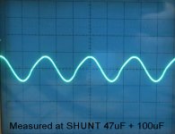
Here the plot of the 1.2V analog after adding a 47uF OS-CON in parallel to the 47uF smd (total about 100uF).
Changing the cables on my table I have reduced also the 50Hz coming from the air.
Here the plot of the 1.2V analog after adding a 47uF OS-CON in parallel to the 47uF smd (total about 100uF).
Changing the cables on my table I have reduced also the 50Hz coming from the air.
Attachments
Last edited:
That's better 🙂Twisted pear had similar problems and bigger caps on output helped.
OK, I'll add a 47-100uF cap in parallel for the two 1.2volt analog shunts.If you add a 100uF 6.3V in parallel to the 47uF smd this oscillation stop and the new measurement give -78dB.
Yep, I think that the Amanero/ES9018 is very sensitive to RFI/EMI.Changing the cables on my table I have reduced also the 50Hz coming from the air.
The following are on my ToDo list:
1. Put the DAC in a case
2. twist all the ac wiring, keep it short and far away from the DAC
3. Add some shielding to the Amanero and the ES9018
Last edited:
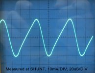
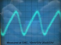
OK, it is not noise, it is oscilation
Here are two measurement as CAAD sugested.
Ripple freq. is around 14Khz.
Here are two measurement as CAAD sugested.
Ripple freq. is around 14Khz.
Attachments
Last edited:
OK, it is not noise, it is oscilation
Here are two measurement as CAAD sugested.
Ripple freq. is around 14Khz.
So now it is ok ?
What is the max value of filter cond. to put in parallel with 47uF / 6V
Can I put bigger then 100uF ? Safe for SHUNT ?
I have some 1500uF/10V with vary low ESR measured. Is this too much ?
Can I put bigger then 100uF ? Safe for SHUNT ?
I have some 1500uF/10V with vary low ESR measured. Is this too much ?
Why is the shunts around 90 C ? I think I will add some copper plate as heatsinks. Lowering the voltage in for them must help a bit ? Could 15 vac in be enough for analog stage ?
What is the max value of filter cond. to put in parallel with 47uF / 6V
Can I put bigger then 100uF ? Safe for SHUNT ?
I have some 1500uF/10V with vary low ESR measured. Is this too much ?
I will try Panasonic FM 1200 uf. 6,3 volts on the shunts for digital. For 3,3 v for analog I will use something else.
I use Lundahl for out. OPAMP output stage is removed on my setup
Shunts for DAC are hot . Looks like bigger filter cap. and 22 ohm instead of 10 ohm will reduce ripple and temperature.
Will test later. Wife is calling ..........
Shunts for DAC are hot . Looks like bigger filter cap. and 22 ohm instead of 10 ohm will reduce ripple and temperature.
Will test later. Wife is calling ..........
I use Lundahl for out. OPAMP output stage is removed on my setup
Shunts for DAC are hot . Looks like bigger filter cap. and 22 ohm instead of 10 ohm will reduce ripple and temperature.
Will test later. Wife is calling ..........
I will try the analog stage but have just finished Balanced Bride Off Zen in highest Quality.
What is the max value of filter cond. to put in parallel with 47uF / 6V
Can I put bigger then 100uF ? Safe for SHUNT ?
I have some 1500uF/10V with vary low ESR measured. Is this too much ?
In theory the capacitor on shunt output terminal should be little to get a fast transient response on load variations.
In practice a shunt with low output capacity on output could be unstable and on my experience sounds bad.
In theorry there is no limit on the value of output capacitor because the CCS of the shunt prevents that pass high current peaks during the charging of the capacitor.
I think 47uF or 330uF are good values.
Why is the shunts around 90 C ? I think I will add some copper plate as heatsinks. Lowering the voltage in for them must help a bit ? Could 15 vac in be enough for analog stage ?
Which type of op-amp are you using ?
I am using OPA 1612 🙂
The quiescent Current (bias) of 2 x OPA1612 op-amp should be about 20mA so it is strange this high temperature on shunt.
If you are using the original transformer you should have 21V on 2200UF capacitor and 14-15V after shunt.
You can reduce the current on shunt chaging R4 and R5 from 10 ohm to 15 ohm or adding a resistor of 33ohm 1W in series to the transformer secondary.
I suggest you to eliminate also R9 and R10 in the shunt.
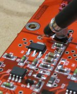
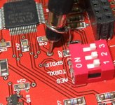
I suggest to desolder a component smd put the soldering iron on the contact side with the larger pcb wire and after few seconds with a screwdriver moved by the component.
The quiescent Current (bias) of 2 x OPA1612 op-amp should be about 20mA so it is strange this high temperature on shunt.
If you are using the original transformer you should have 21V on 2200UF capacitor and 14-15V after shunt.
You can reduce the current on shunt chaging R4 and R5 from 10 ohm to 15 ohm or adding a resistor of 33ohm 1W in series to the transformer secondary.
I suggest you to eliminate also R9 and R10 in the shunt.
I suggest to desolder a component smd put the soldering iron on the contact side with the larger pcb wire and after few seconds with a screwdriver moved by the component.
It is not my shunt. It is what I am told by another member. My dac is not finished. I am waiting for the green light ! 🙂 Anyway I have changed 50 components allready because I do not like minimelf and ceramic caps. Everything with magnetic leads must go. 33 ohm in series with transformer. I like that. I use that trick a lot.
Last edited:
yes!
some day later i will ship it!
thanks you waite!~
thank you & please dont forget to update the firmware to the latest version & declare lower value.
Last edited:
Hi Quanghao
can you please include 5 buttons with the shield when you will ship it?
I will pay for them and for the shipping
Thank you
can you please include 5 buttons with the shield when you will ship it?
I will pay for them and for the shipping
Thank you
Hi Quanghao
can you please include 5 buttons with the shield when you will ship it?
I will pay for them and for the shipping
Thank you
Me too .. I want the buttons with my DAC shipment.
Quanghao, pls inform me how much I have to pay for the buttons.
ATTENTION: corrections on op-amp module and DAC module
1) It is necessary reduce the current on shunt changing R4 and R5 from 10 ohm to 15 ohm because now the temperature of the second smd transistor is very high. Quanghao can send you the 4 x 15ohm smd resistors to make this simple correction.
2) Eliminate also R9 and R10 in the +15V and -15V shunt.
3) Add a 47uF or 100uF capacitor in parallel to the original 47uF on the 1.2V analog (L & R) near the jump to eliminate the little oscillation.

- Status
- Not open for further replies.
- Home
- More Vendors...
- Quanghao Audio Design
- DAC-END R (ES9018) full assembled board