These two beauties going to a local friend! 😎
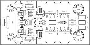
Is it a prinitng mistake on those capacitors - 6.3 volt 2200mfd.?
I can imagine Deepawali while powering on with 30volts rail .
Is it a prinitng mistake on those capacitors - 6.3 volt 2200mfd.?
I can imagine Deepawali while powering on with 30volts rail .
No, these are feedback caps and are not exposed to full rail voltage.
Is it a prinitng mistake on those capacitors - 6.3 volt 2200mfd.?
I can imagine Deepawali while powering on with 30volts rail .
Hi Jayadev.
They face less than 3V at any time with any PS voltage or output level. 😉
Deepawali is months away, no need to imagine it now... 😀
cheers.
Oops,My bad!No, these are feedback caps and are not exposed to full rail voltage.
Btw ,why do we have such huge capacitors for feedbacks?
What are we feeding,I couldn't find the schematics for it yet-new arrival.
Apologies, if I am going OT.
Oops,My bad!
Btw ,why do we have such huge capacitors for feedbacks?
Coz the gain setting resistor is such low; 100ohms only. Plus better ripple filtering of the input bias current from the PS rails.
What are we feeding
Emitters of the input transistors. Symmetrical AC feedback signal from the output.
I couldn't find the schematics for it yet-new arrival.
Apologies, if I am going OT.
Check the first post. There is the schematic.

Mr. Shaan or jr. I would love to make my own pcb,s but my hands are in such a state of uselessness that it would be a joke to even try. Evette
Hi evette.
Apologies if I have said something rude.
I'm sure you can get ready PCBs from Pete or Jason or someone who have some easy to setup boards at hand.
All the best.
shaan
Apologies if I have said something rude.
I'm sure you can get ready PCBs from Pete or Jason or someone who have some easy to setup boards at hand.
All the best.
shaan
No apologie is needed sir.. My hands are such that I put solder in my mouth any line it up with the parts on pcbs then solder with my good hand. My little Evette thinks her daddy is crazy. She doesn,t know it but she,s not far offthe mark,,LOL Joe
PeeCeeBee/Through-Hole VSSA
@evette (and anyone else interested in the through-hole-only version)
I've had a couple requests for more boards, but I can't gauge how much interest there is in my layout, there are so many good alternatives...
In any case, a revision is in the works... 😀
Another revision of my layout is in progress, to have a bit more flexibility in components used, various options, and correcting some annoying drill size issues. However, I would encourage everyone to investigate the different versions which are available here and in other threads in the forum. There is lots to choose from!
There are several posted here, and more alternative versions of LazyCat's circuit in other threads. Almost every one I look at has some good idea or twist on the basic VSSA toplogy.
I would also point out that LC is continuing to sell the original VSSA modules with SMD components in the original VSSA thread, now graduated to the official Vendors Forum, and busy working on a new version (recommended). Looks like VSSA will soon be a complete product line!
Currently I have two versions of my board from the PeeCeeBee schematic, and one set of the original VSSA modules from LC's Group Buy. The sound from all of them is very good, but there are some limitations and differences with each one. As they say, YMMV ( your mileage may vary... 😀 ).
I am currently testing a higher-voltage version with MrEvil's Cap Multiplier Power supply. (Same supply I plan to try with Shaan's latest circuit, when I get that far).
The pics below show my most recent test configuration, with LazyCat's original SMD VSSA module on the left of the PeeCeeBee Chassis, for comparison.
Attachments

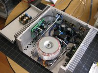
LazyCat's original SMD VSSA module on the left of the PeeCeeBee Chassis, for comparison.
If there is an amp that can beat the sonics of VSSA, then it's only the VSSA. 😉
Very well put, (chuckle).If there is an amp that can beat the sonics of VSSA, then it's only the VSSA. 😉
In all fairness, since I have had a chance to look more closely at the VSSA modules, there are some small but interesting improvements over the published version, the Cat does not give away all his secrets (not should he, in my opinion).
Among other things, LC ships his modules with KSC/KSA VAS transistors that test very close as a pair, compared to anything else I have on the shelf that is not matched by hand. The Alfets he ships are hard to come by for most people, and based on notes from the manufacturer, even they are having trouble building them to spec.
There are also some basic differences, which make the PeeCeeBee versions easier to deal with for diy purposes. The PeeCeeBee variants are easier to set up and calibrate. LC recommends two meters for his modules for a good reason (I've done it both ways, two meters win, hands down). Output bias is very touchy compared to both versions of your circuit that I have, or compared to other diy boards (not sure why).
There is no input cap, VSSA is direct coupled. The modules ground to the heatsink through screws used to mount the VAS transistors, and the grounding scheme as published in the VSSA thread is not very conventional, and perhaps optimized to the use of two independent switching supplies. Those alone cost around 100 Euro (each).
I still listen to the first boards made from your schematic almost every day, btw. Lower supply rails than my test set, no parallel caps, only difference is an extra 1000uF on the rail... I listen to my test set (in pics above) also, obviously, but it is disassembled and in a state of flux more often than not... 😉
The Alfets he ships are hard to come by for most people, and based on notes from the manufacturer, even they are having trouble building them to spec.
Now, imagine how much trouble there would be for the buyer if that Alfet should die! I think that for diy purposes nothing beats separate output Latfets.
BTW, have you measured bandwidth of your PeeCeeBee with both input low pass filter and Zobel installed?
Yes, although I have not posted everything I tested. The high end is difficult to measure with Zobel installed, and my signal generator has issues at high frequency.Now, imagine how much trouble there would be for the buyer if that Alfet should die! I think that for diy purposes nothing beats separate output Latfets.
BTW, have you measured bandwidth of your PeeCeeBee with both input low pass filter and Zobel installed?
With no Zobel, the 3db point is around 1.3MHz.
Posted in VSSA thread
(as part of another discussion)
At high frequency, the Zobel cap is essentially a short to ground, so you have the output waveform, backed up by almost unlimited power, across a 1W resistor. So, at most you can use about 1/2-1Vrms at the output for testing. At 27db gain, I have to adjust the input very low, and doing a reliable measurement of the -3db point becomes difficult. It will be close to the 1.3MHz without Zobel, which is so high that you can receive radio on a dangling cable (tested, and have the burned Mosfets for proof!)
Hi PMI, nice info on comparing LC VSSA with our beloved Peeceebee.
if you made revision on your peeceebee version please upload it here.
till now i've tried Shaan's and yours Peeceebe Layout with minor mod. to fit my parts.
both supplied with diy smps 🙂 and sonically very very good
if you made revision on your peeceebee version please upload it here.
till now i've tried Shaan's and yours Peeceebe Layout with minor mod. to fit my parts.
both supplied with diy smps 🙂 and sonically very very good
I'll do that as soon as I am finished. I had to stop for a while to work on other things, but yes, I am planning on it. Time has been in short supply, and of course, it is summer here... I need to get my dose of Vitamin-D for the whole year in the space of a few weeks... 🙄😀Hi PMI, nice info on comparing LC VSSA with our beloved Peeceebee.
if you made revision on your peeceebee version please upload it here.
till now i've tried Shaan's and yours Peeceebe Layout with minor mod. to fit my parts.
both supplied with diy smps 🙂 and sonically very very good
...which is so high that you can receive radio on a dangling cable (tested, and have the burned Mosfets for proof!)
Have seen the speaker talking AM stations with most CFAs I built. Trick- remove the pF at the input and zobel at the output, take a twizzer and touch the input pin with it, become an antenna, listen to radio stations.
note- no responsibility for blown transistors will be taken. 😀
Output bias is very touchy compared to both versions of your circuit that I have, or compared to other diy boards (not sure why).
The glass diodes at work.

With no Zobel, the 3db point is around 1.3MHz.
Hi Pete.
Can you trace the HF limit without the input RF suppression cap installed? Or maybe with, say, 10pF in place of it (15MHz limit)? Will be great to know.
Thanx.
@evette (and anyone else interested in the through-hole-only version)
I've had a couple requests for more boards, but I can't gauge how much interest there is in my layout, there are so many good alternatives...
In any case, a revision is in the works... 😀
Another revision of my layout is in progress, to have a bit more flexibility in components used, various options, and correcting some annoying drill size issues. However, I would encourage everyone to investigate the different versions which are available here and in other threads in the forum. There is lots to choose from!
There are several posted here, and more alternative versions of LazyCat's circuit in other threads. Almost every one I look at has some good idea or twist on the basic VSSA toplogy.
I would also point out that LC is continuing to sell the original VSSA modules with SMD components in the original VSSA thread, now graduated to the official Vendors Forum, and busy working on a new version (recommended). Looks like VSSA will soon be a complete product line!
Currently I have two versions of my board from the PeeCeeBee schematic, and one set of the original VSSA modules from LC's Group Buy. The sound from all of them is very good, but there are some limitations and differences with each one. As they say, YMMV ( your mileage may vary... 😀 ).
I am currently testing a higher-voltage version with MrEvil's Cap Multiplier Power supply. (Same supply I plan to try with Shaan's latest circuit, when I get that far).
The pics below show my most recent test configuration, with LazyCat's original SMD VSSA module on the left of the PeeCeeBee Chassis, for comparison.
Very nice build PMI!
- Home
- Amplifiers
- Solid State
- PeeCeeBee