Hello there, I've been leaning towards building an omni but since so many likes the dipole I thought I'd build a decent enough one before I diss them so I can compare 😉
The big question of baffles came up where the move the more knowledgable (John & Linkwitz) is to get smaller drivers and baffles and work them under the dipole peak. I already have drivers so I thought I'd start with them which is a 6.5 inch midrange ( TD6M ). Ideally I'd be able to cross it high, at say 3 khz with maybe some extra tweeters on the back to even up front rear dispersion.
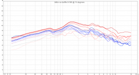
The big issue is of course that the dipole peak will be smack in the middle at 1.5 khz. I tested the driver naked without a baffle and efficiency is a big no-no and the dipole peak is right there. Response over 1 khz is very uneven where it should be a consistent null. The driver itself has a 700 - 1000 hz dip but that can be filled in with some EQ.
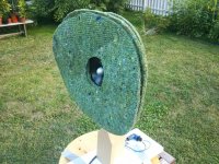
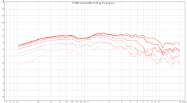
The thing I tested though was to slab a gigantic wool carpet baffle. Keep in mind that this is a very ugly one, there is no nice chamfer around the drivers since I just made something to test. It is not straight so the null is at about 75 degrees instead of 90.
It does show very interesting results though: The low end senstivity is massively increased and this is without lowering the dipole peak. The actual peak itself is even smoothed out and isn't so hard to handle anymore.
Next step is to build the draft of the real speaker since the results were so promising and hope that it still shows promise when I add the other drivers. The current idea is to have 4 cone tweeters, 1 in the front crossed at 3 khz and 3 in the back to help raise the rear response from 1.4 khz.
Addition: In the graphs the most red line is 0, the most blue line is 180 and 90 is grey. Then each step from pure red to grey and from grey to pure blue is 15 degrees.
EDIT: Zoomed in graphs with split front-back are a few posts down.
--------------------------------------------------------------------
EDIT2: The findings in this thread compiled here in the first post:
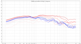
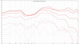
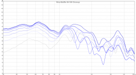
In this post I did a wood baffle of the same dimensions as the wool one.
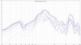
The wood baffle measures as predicted from the Edge, big gain in low frequencies but the response goes nuts as predicted in the Edge so isn't usable full range in any shape or form. If we use the wool baffle instead we get withing 1 dB error the same low frequency gain but none of the dipole peak issues as I show in a combined picture in this post.
My theory is that we can think of the sound as water, with a solid baffle the water falls off the sides creating a waterfall at the edges. This means that all water passes exactly around the edge which creates the big anomalies in the repsonse.
Based on my observation i'd assume that the sound just wants to travel the cheapest way to the other side. Because the whole baffle is lossy we can think of it as a filter: some sound will pass everywhere but if sound has already saturated an area it is cheaper to find a new area of the baffle not yet saturated. In the end there is no single point where all sound passes and thus the dipole peak is spread over the whole range, thus disappearing.
The big question of baffles came up where the move the more knowledgable (John & Linkwitz) is to get smaller drivers and baffles and work them under the dipole peak. I already have drivers so I thought I'd start with them which is a 6.5 inch midrange ( TD6M ). Ideally I'd be able to cross it high, at say 3 khz with maybe some extra tweeters on the back to even up front rear dispersion.
The big issue is of course that the dipole peak will be smack in the middle at 1.5 khz. I tested the driver naked without a baffle and efficiency is a big no-no and the dipole peak is right there. Response over 1 khz is very uneven where it should be a consistent null. The driver itself has a 700 - 1000 hz dip but that can be filled in with some EQ.
The thing I tested though was to slab a gigantic wool carpet baffle. Keep in mind that this is a very ugly one, there is no nice chamfer around the drivers since I just made something to test. It is not straight so the null is at about 75 degrees instead of 90.
It does show very interesting results though: The low end senstivity is massively increased and this is without lowering the dipole peak. The actual peak itself is even smoothed out and isn't so hard to handle anymore.
Next step is to build the draft of the real speaker since the results were so promising and hope that it still shows promise when I add the other drivers. The current idea is to have 4 cone tweeters, 1 in the front crossed at 3 khz and 3 in the back to help raise the rear response from 1.4 khz.
Addition: In the graphs the most red line is 0, the most blue line is 180 and 90 is grey. Then each step from pure red to grey and from grey to pure blue is 15 degrees.
EDIT: Zoomed in graphs with split front-back are a few posts down.
--------------------------------------------------------------------
EDIT2: The findings in this thread compiled here in the first post:
In this post I did a wood baffle of the same dimensions as the wool one.
The wood baffle measures as predicted from the Edge, big gain in low frequencies but the response goes nuts as predicted in the Edge so isn't usable full range in any shape or form. If we use the wool baffle instead we get withing 1 dB error the same low frequency gain but none of the dipole peak issues as I show in a combined picture in this post.
My theory is that we can think of the sound as water, with a solid baffle the water falls off the sides creating a waterfall at the edges. This means that all water passes exactly around the edge which creates the big anomalies in the repsonse.
Based on my observation i'd assume that the sound just wants to travel the cheapest way to the other side. Because the whole baffle is lossy we can think of it as a filter: some sound will pass everywhere but if sound has already saturated an area it is cheaper to find a new area of the baffle not yet saturated. In the end there is no single point where all sound passes and thus the dipole peak is spread over the whole range, thus disappearing.
Attachments
Last edited:

OllBoll, quite nice!
Did you try with just one sheet of wool?
Please, show 0-904 and 90-180¤ responses in separate graphs. Now there are too many intersecting lines. To me your responses show that dipole function is perfect at 600-700Hz, but with the felt you loose directivity above it (700-1300Hz),
With a nude driver you have uniform directivity up to 2500Hz (dipole null), which means that you should set xo around 2000Hz. Then the overlapping output of the tweeter helps to cover wiggles above dipole null of the woofer.
With dipoles, there is no way to extend both low and high range simultaneously! You must choose one or other. Sorry!
And of course you need areal woofer below that 6,5"
Last edited:
Nope. sadly I only tried with three sheets.
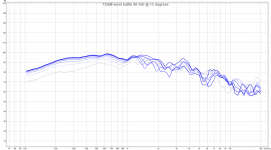
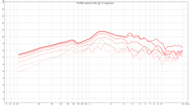
And here are new images with split front-back responses to simplify reading them:
On the front the dispersion is kinda nice up to 2 - 3 khz so the original plan is to cross somewhere there to the two main tweeters. On the rear of course the response doesn't extend that high so the plan was to add two extra tweeters pointing back to help from 1.4 khz and lowpass them at the main tweeter XO.
And yes, the 6.5" is to be crossed at 300 where a 10" is taking over =)
The big question about if this scales up is how the tweeter transistion will be, right now the loss of a dipole peak might mostly have to do with that the rear dispersion at the peak is far worse than the front.
If that doesn't work gracefully then the best solution is probably to cross to 3 inch midranges at 1 - 1.4 khz.
Attachments

Last edited:
Interesting idea, I'm not quite sure what to make of it. A lossy baffle? Hmmm....
Thanks very much for doing all the measurements and posting them here, that's a great help.
Is it possible to show a reduced vertical scale? Your 150dB scale makes the curves look very nice, but it's difficult to get an impression from them. 🙂
Thanks very much for doing all the measurements and posting them here, that's a great help.
Is it possible to show a reduced vertical scale? Your 150dB scale makes the curves look very nice, but it's difficult to get an impression from them. 🙂
Is it possible to show a reduced vertical scale? Your 150dB scale makes the curves look very nice, but it's difficult to get an impression from them. 🙂
Ask and you shall recieve =)
The interesting thing is that the baffle is about 50 cm wide, so if it was solid it should have been a peak at about 233 hz, with the baffle we get over 10 db more efficiency at 300 but no dipole peak there =)
Even if you don't extend further than the naked driver dipole peak this seems to be a cheap way to increase the efficiency down low with as far as I can se no real disadvantages since up to about 1.2 khz the response is almost the same as naked but with much much more efficiency.
Except that some might argue that it is very ugly 😀
The current plan is to design the speaker like the Nao Note II RS with a frame around and instead of having a hole in the frame like the Note fill it up with wool carpet.
Attachments

Last edited:
Thanks! That really shows the differences. I wonder why no peak? Do you think it's the material? Might have to run the sims in software to see what's going on.
BTW, nice to see that you use speakON connectors.
BTW, nice to see that you use speakON connectors.
Thanks! That really shows the differences. I wonder why no peak? Do you think it's the material? Might have to run the sims in software to see what's going on.
BTW, nice to see that you use speakON connectors.
My guess of why there is no peak:
On a hard baffle there is one magical place where all sound goes around, which creates large peaks and nulls.
Here on the lossy baffle there is no single point where the sound wave have can cheaply travel through the baffle since the sound will probably try to find the most cheap place. In the end we could visualise it as water:
If you have a flat filter over an area and drop a stream of water in the middle the water will spread out since it is cheaper to find a place where water currently isn't already saturating the filter.
In the end since there is no single point where all the sound waves turn around there is no single peak / null but spread enough do disappear.
And yes, I absolutely hate fiddling with screw connectors so speakON it is, never have to be afraid of messing up polarity either =)
My impression is that of a "waveguide/anti-diffraction" device. I would suppose that the wool could be mounted to a wire ring allowing shape manipulation in 3D ... might have some interesting frequency responses as well?

Thanks. The Edge software shows me a naked driver response very similar to your measurement, but a 500mm round baffle sims very differently to what you get with the wool baffle.
Even more interesting is that the 300 hz sensitivity gain is almost the same as simulated with that hard baffle, that for one is something I did not expect.
Yep. Of course we hope that you will build a plywood baffle of the same size and shape then show us the measurements. 😀 That would really tell us something.
My guess of why there is no peak:
On a hard baffle there is one magical place where all sound goes around, which creates large peaks and nulls.
Here on the lossy baffle there is no single point where the sound wave have can cheaply travel through the baffle since the sound will probably try to find the most cheap place. In the end we could visualise it as water:
If you have a flat filter over an area and drop a stream of water in the middle the water will spread out since it is cheaper to find a place where water currently isn't already saturating the filter.
In the end since there is no single point where all the sound waves turn around there is no single peak / null but spread enough do disappear.
And yes, I absolutely hate fiddling with screw connectors so speakON it is, never have to be afraid of messing up polarity either =)
Very nice analogy and concur with your thoughts. Also sure that when you do a bit of shaping/thinning etc will further improve your results.
Circular baffle is the way to get a very deep dipole null and lobing above it. All directions have same distance to the edge. A rectangular baffle distributes distance to the edge --> distributes nulling frequency.
Dipoels are strange animals, I've been trying to understand them for half a year now! It's like whispering to horses - you must learn their (body) language and start thinking like them! 😎
Dipoels are strange animals, I've been trying to understand them for half a year now! It's like whispering to horses - you must learn their (body) language and start thinking like them! 😎
The Finnish speaker guru Pekka Tuomela designed a dipole speaker based on SEAS 18 coaxial about 6 years ago. MB CXD rakennussarja - Hifitalo
I have never heard it, but I have might have the original article in my bookshelf. If I remember right, xo is wel above 2kHz, which means loosing grip of directivity above 1kHz in original baffle.
I have never heard it, but I have might have the original article in my bookshelf. If I remember right, xo is wel above 2kHz, which means loosing grip of directivity above 1kHz in original baffle.
An externally hosted image should be here but it was not working when we last tested it.
Last edited:
Oval shaped helps too 😉Circular baffle is the way to get a very deep dipole null and lobing above it. All directions have same distance to the edge. A rectangular baffle distributes distance to the edge --> distributes nulling frequency.
Dipoels are strange animals, I've been trying to understand them for half a year now! It's like whispering to horses - you must learn their (body) language and start thinking like them! 😎
Same issue most have understanding women 😀
One of the things that make me extra excited about how the efficiency is massively increased is because I wanted a dipole with 92+ dB efficiency so I could power it with flea amps =)
With a standard dipole It'd be impossible but with the wool baffle it just might work.
With a standard dipole It'd be impossible but with the wool baffle it just might work.
Again, I hope you can do a plywood baffle and show us the difference vs wool.
I"m already looking for wool pads or felt to do some experimenting.
I"m already looking for wool pads or felt to do some experimenting.
Awesome work! I love using absorbtion, it's not pretty but gives an extra dimension in acoustc design. I'm really picky about diffraction and so use wool, foam, etc a lot
- Status
- Not open for further replies.
- Home
- Loudspeakers
- Multi-Way
- Dipole wool carpet baffle experiment