DAC shield:
1. sipo75
2. Domi_78
3. bobkojek
4. Erlend Sæterdal
5. danielkol*2
7. kmajjo * 6
8. xtomm
9. MattMax
10. Gricko
11. Luizl
12. Misterrogers
13. randytsuch
14: CAAD
15: glt
16: axeexa(antony_shih)
17: bertchai
18: TarnishedEars
19: smoothquark (with complete DAC)
20: rliyung/raoul
21: masterkey (with complete DAC)*
22: danny_66
23: yildiray
24: Boxi80
25: halook*
26: kgkim * 6
27. rredline**
28. la1209
29. kimgiin
30. NicMac
I did try the Toslink input on mine but it was not able to lock upper than 44.1 KHz.
- This may be due to my long (10 meters) and cheap optical fiber.
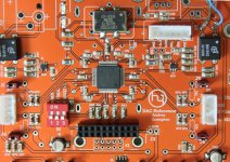
The smc marked "C14A" is a LMV7219 from TI
Comparing circuit to schematic, this is what I think
C36 is C7
R13 is R63
R15 is R66
BTW, since C36 is removed, now R63 and R66 are in parallel
R14 is R60
What happened to R68? Looks like someone reworked it.
R16 is R54
Not sure why it is not working though.
Also funny you can't get toslink working above 44k.
Optical shouldn't care about the length too much. I am using a cheap monoprice optical cable. I haven't listened too much to this input, but it worked no problem, and as soon as I put in a 96k song, it locked on, and indicated 95k on the display.
Randy
Quanghao:
Could you please provide us with a part-number for the connector that you are using between the DAC and the I/V board? I'd really like to source some spares for experimentation with different types of output stages.
Could you please provide us with a part-number for the connector that you are using between the DAC and the I/V board? I'd really like to source some spares for experimentation with different types of output stages.
So I am not using SPDIF, mostly I use USB, and I can use to toslink but I don't plan to use it much.
But, if I wanted to use SPDIF, I would cut the trace across C36, and install a small cap there. I think a 10nf would work.
Reason is that with C36 shorted, R63 and R66 are in parallel, and this creates a resistor very close to 75 ohms.
R66 is part of a resistor divider network designed to generate the correct voltages for the 7219 voltage comparator to operate. I don't expect that it is working properly with an R66 that is effectively close to 75 ohms, R66 should be 10k.
Somebody want to try my theory?
Randy
Quanghao:
Could you please provide us with a part-number for the connector that you are using between the DAC and the I/V board? I'd really like to source some spares for experimentation with different types of output stages.
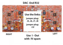
Invite you to see this picture. Please try 2 sound modes:
1. DAC with: I - Out
2. DAC with: V - Out
Thank you, and tell me the sound of the 2: I-out and V-out
Attachments
So I am not using SPDIF, mostly I use USB, and I can use to toslink but I don't plan to use it much.
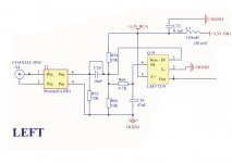
I have had many tests showed, remove capacitors in this position, it will sound better.
Take a look at the circuit diagram
Attachments
So I am not using SPDIF, mostly I use USB, and I can use to toslink but I don't plan to use it much.
I have had many tests showed, remove capacitors in this position, it will sound better.
Take a look at the circuit diagram
Hi Quanghao,
The problem is some of us certainly require spdif/coaxial to accept 96kHz or higher
So I am not using SPDIF, mostly I use USB, and I can use to toslink but I don't plan to use it much.
I have had many tests showed, remove capacitors in this position, it will sound better.
Take a look at the circuit diagram
Maybe it does sound better, I haven't (and most likely won't) compare, so I cant comment.
But, looking at removing the cap, it is messing up the comparator circuit. I'm sure the circuit wasn't designed to have the 75ohm in parallel with the 10k resistor.
This could well be why you can't get over 96k, I thought the es9018 would do it, and was surprised when you said that 96k was the limit. I would also guess it is marginal at 96k and depends greatly on the source. Seems like most sources are not working at 96k with this circuit.
Randy
SPDIF INPUT WORK AT 96KHZ OR HIGHER
Hi Quanghao,
The problem is some of us certainly require spdif/coaxial to accept 96kHz or higher
As told before the spdif inputs of this DAC accept without problems 96KHz or higher.
I have tested the spdif input with M-Audio Transit (optical) and Tener TE7022 module (coax).
If your source is not able to drive the standard spdif load (75 ohm) remove the R63 resistor and test it.
The lmv7219 amplify and square the spdif input to convert it to a TTL 3.3V signal so C36 is necessary for the correct functionality of the circuit.
In some cases abnormal ciruit modifications can create a better sound. 🙂
Last edited:
The lmv7219 amplify and square the spdif input to convert it to a TTL 3.3V signal so C36 is necessary in the circuit.
In the production version of the dac, C36 is shorted (trace runs across the pads), and not installed.
In the production version of the dac, C36 is shorted (trace runs across the pads), and not installed.
ok, I will check it on my prototype and I will simulate the input circuit in both conditions.
DAC shield:
1. sipo75
2. Domi_78
3. bobkojek
4. Erlend Sæterdal
5. danielkol*2
7. kmajjo * 6
8. xtomm
9. MattMax
10. Gricko
11. Luizl
12. Misterrogers
13. randytsuch
14: CAAD
15: glt
16: axeexa(antony_shih)
17: bertchai
18: TarnishedEars
19: smoothquark (with complete DAC)
20: rliyung/raoul
21: masterkey (with complete DAC)*
22: danny_66
23: yildiray
24: Boxi80
25: halook*
26: kgkim * 6
27. rredline**
28. la1209
29. kimgiin
30. NicMac
31.vitalica *2 pcs
As told before the spdif inputs of this DAC accept without problems 96KHz or higher.
I have tested the spdif input with M-Audio Transit (optical) and Tener TE7022 module (coax).
If your source is not able to drive the standard spdif load (75 ohm) remove the R63 resistor and test it.
The lmv7219 amplify and square the spdif input to convert it to a TTL 3.3V signal so C36 is necessary for the correct functionality of the circuit.
In some cases abnormal ciruit modifications can create a better sound. 🙂
Hi audiodesign,
FYI, I have tested the coaxial input of my purchased DAC-END R but no luck with 96kHz or higher, with the following:
1. Coaxial output of my desktop PC
2. A TE7022 based USB to coaxial converter.
Both of the above work perfectly with frequencies up to 192kHz with my current Audiolab MDAC, which is also an ES9018 based DAC.
ok, I will check it on my prototype and I will simulate the input circuit in both conditions.
The circuit work with and without the input capacitor C36.
In any case the output is a good TTL signal at 3.3V.
Attachments
Last edited:
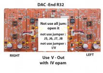
Invite you to see this picture. Please try 2 sound modes:
1. DAC with: I - Out
2. DAC with: V - Out
Thank you, and tell me the sound of the 2: I-out and V-out
I will definitely try it both ways. Thanks for the diagram! That is very helpful!
However I would also like to try the DAC with a tube output stage, as well as a transformer output (among other things). But I need to find some more of those 4-pin connectors to be able to do this without soldering to the main-board.
So could you please tell us what these 4-pin connectors are called, so that those of us who really want to experiment can order some extras?
Thanks again!
Hi Andrea,
- What are the results of your tests on prototype ?The circuit work with and without the input capacitor C36.
In any case the output is a good TTL signal at 3.3V.
Just for info, I noticed that Hifiduino has a pre-production board (I believe). His board's C36 has a cap and C35 has a resister (?) and Crystek CCHD-950-100 osci.
This is what he claimed:
"I tried several sample rates through the SPDIF interface and also tried up to 352K/384K sample through the I2S interface. Also tried DSD-64 and DSD-128 through the same serial interface (don’t have any DSD higher than 128). Every sample rate and format was supported without a glitch (Some may recall that with the 80Mhz clock, playing 352K and 384K had noise glitches)"
ES9018 “DAC-END R” Fully Assembled DAC | H i F i D U I N O
Attachments
Hi,
On hifiduino.wordpress.com we can read :
"Had to fix the code in order to make it work. I discovered a couple of things on how the Sabre32 DAC chip behaves:
When switching from SDPIF input to Serial input, it is not sufficient to switch the input format. One must also switch the SPDIF MUX to an input that does not have a live SPDIF signal (I switched it to SPDIF#1 which is shared with the I2S connections). If you do not do this step, the status register will report an SPDIF data stream even though you are receiving an I2S stream, and the sample rate calculation will be completely wrong. However, this has no effect on the sound.
“Auto SPDIF detection” must also be set in the registers when using any of the SPDIF inputs. It is not sufficient to just select the SDPIF input port. If you do not do this step, the DAC will not receive the SPDIF data stream.".
- I am not a specialist but is our Reference DAC concerned with these issues ?
- I notice that a resistor is installed instead of a cap at C35 location and a cap is installed at C36 location on his PCB.Just for info, I noticed that Hifiduino has a pre-production board (I believe). His board's C36 has a cap and C35 has a resister (?) and Crystek CCHD-950-100 osci.
This is what he claimed:
"I tried several sample rates through the SPDIF interface and also tried up to 352K/384K sample through the I2S interface. Also tried DSD-64 and DSD-128 through the same serial interface (don’t have any DSD higher than 128). Every sample rate and format was supported without a glitch (Some may recall that with the 80Mhz clock, playing 352K and 384K had noise glitches)"
ES9018 “DAC-END R” Fully Assembled DAC | H i F i D U I N O
On this nearby photo , two caps are installed beside the output connector and the pulse transfo looks deferent from your photo.
Last edited:
- Status
- Not open for further replies.
- Home
- More Vendors...
- Quanghao Audio Design
- DAC-END R (ES9018) full assembled board