Lucky find !
I just decided I am going to go full steam ahead with my "project"
(which is similar to yours)
Thanks (!!) for the inspiration. I'm glad I found this thread.
I have a 3-way Altec VOT with active sub - Altec 288-8G for the 1505, GPA 515-8G woofers/828 cabinets, Rythmik 15HP subs and JBL 2404H horn tweeters.
I use an active crossover at 50Hz, 500Hz, and passive 1st order at 15KHz for the horn tweeters; biamped using We 91a 300b monoblocks, 26 tube preamp, Tetra Sans Phono Preamp, Gyro SE TT and Marantz SA-KI Pearl CD for source.
Very happy with the sound produced.
I just decided I am going to go full steam ahead with my "project"
(which is similar to yours)
Thanks (!!) for the inspiration. I'm glad I found this thread.
Here is current idea. 8^ft box, ported to the bottom of the cabinet. I figured I could play with tuning by raising or lowering the box.
Attachments
Sorry. Just posted this in Beyon Ariel thread. IT seem to have a lot of tuning flexiblity simply by changing port length or stuffing. Also, being down firing port, lends itself to the idea of using the Hirage box as suggested by Line Source. It would simply be a matter of raising or lowering the speaker off the ground.
Caveat: This was designed for my drivers.
Caveat: This was designed for my drivers.
Attachments
I am interested, as my current designs will port to the bottom of the cabinet.
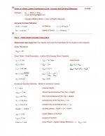
GPA604III Hiraga MLTL Design Goals:
With room gain, flat to 27Hz, the low A of a piano.
A 22" wide baffle allowing large round-overs to reduce 1Khz woofer diffraction.
-MDF quarter rounds with 3" to 6" radius are widely available.
Volume= 12 ft^3
Cross Section Area = 405 in^2
Height = 53"
Depth = 18.4"
Width =22" = 200Hz baffle step = allows large edge radius for reduced diffraction
Speaker center at 17.3" down from top. ~ 32.7% of TL height
Port equal to 6" diameter pipe, 4" long. Approximated by 0.8" high slot on 3-bottom edges F+L+R. Back edge is sealed.
One long top-to-bottom, front-to-rear, slotted cross brace.
Three short left-to-right cross braces.
I will be using the above simm'd box to try the Hiraga design. I have wanted a down firing port from the beginning, so I figure I can try for free. Cant have a box 53" tall, as I have to put a horn on top. IT makes perfect sense in that application, as it is a coax and the speaker will be perfect hieght of about 32-36", at least for most rooms. For my box, the same pointin the vertical plane will be splitting the woofer and horn.
GPA604III Hiraga MLTL Design Goals:
Port equal to 6" diameter pipe, 4" long. Approximated by 0.8" high slot on 3-bottom edges F+L+R. Back edge is sealed.
One long top-to-bottom, front-to-rear, slotted cross brace.
Three short left-to-right cross braces.
Unfortunately, I'm poor in trying to figure out how the slot would look like.🙁 Would it be possible to illustrate this in some kind of drawing or picture? Thanks.
Would it be possible to illustrate this in some kind of drawing or picture? Thanks.
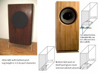
One of the favorite Altec604 cabinets has a bottom pipe port which requires long legs to adequately lift it above ground. The leg height is often adjustable for bass tuning. This design wastes a great deal of potential cabinet volume. An Altec604 cabinet with a bottom slot port could gain extra cubic feet of useful volume over the leggy design. A 6" diameter pipe port has 28in^2 area, which a 22"wide x1.3"high bottom slot port can provide with less wasted internal cabinet volume. If the lower slot port cabinet board is cut out, then a properly shaped lift-shim board on a plinth base that effectively increases the slot port area can change the tuning.
Interesting added-volume idea to play with.
Attachments
One of the favorite Altec604 cabinets has a bottom pipe port which requires long legs to adequately lift it above ground. The leg height is often adjustable for bass tuning. This design wastes a great deal of potential cabinet volume. An Altec604 cabinet with a bottom slot port could gain extra cubic feet of useful volume over the leggy design. A 6" diameter pipe port has 28in^2 area, which a 22"wide x1.3"high bottom slot port can provide with less wasted internal cabinet volume. If the lower slot port cabinet board is cut out, then a properly shaped lift-shim board on a plinth base that effectively increases the slot port area can change the tuning.
Interesting added-volume idea to play with.
Thank you very much! Might look into changing the Altec 620A that I'm listening to right now.
Line Source. I cannot see how the Hiraga design is not downward firing port with a base to increase total surfece area. Wouldn't it be just like mounting a down firing port close tot he ground?
There are many genius loudspeaker designers using clever science to create fantastic sounding speakers. I have never built a "perimeter slot" port that goes around several bottom cabinet sides.
The text book mathematical models that I use for bass reflex port design assume that there is no significant air flow restrictions at either end of the port. I believe this is why Altec604 cabinets with bottom ports include legs to lift the cabinet bottom 1.5x to 2x the port diameter above the floor... to avoid restricted air flow.
The port models I have studied include correction calculations for port construction variations like flared pipe end(s), rectangular, oval, near floor, near box corner, sheve-port, etc... A MLTL design has critical port location plus critical stuffing demands for optimal performance. Most MLTL designs are very tall with pipe ports near the bottom, and require no stuffing near the port.
Some discussion and modeling on MLTL designs with a bottom rectangular slot/shelve port could help increase the internal stuffed TL volume at reduced box height.
Last edited:
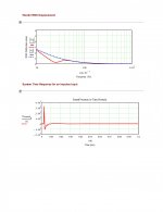
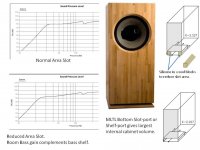
Dropped picture showing normal slot port area SPL, and reduced slot port area SPL with some bass shelf effect which the room's bass gain is expected to complement toward flat'ish.
From building and measuring a couple MLTL designs I have learned that there is both science and art to stuffing a TL. Your favorite stuffing material may be different than what the simulator expected. I do not know what a bottom shelve port on an MLTL would sound like... just that it would maximum internal volume.
From building and measuring a couple MLTL designs I have learned that there is both science and art to stuffing a TL. Your favorite stuffing material may be different than what the simulator expected. I do not know what a bottom shelve port on an MLTL would sound like... just that it would maximum internal volume.
Attachments
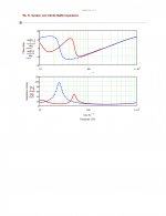
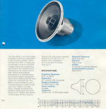
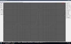
Has anyone measured the tweeter section of the 604E? I am seeing that they are typically crossed over at around 1500Hz but I am measuring a large resonant peak right on 2KHz.
Ordinarily this does not lend itself to a 1500Hz crossover point regardless of the slope.
Any thoughts?
Ordinarily this does not lend itself to a 1500Hz crossover point regardless of the slope.
Any thoughts?
What's an 8 dB rise in the 1/3 octave from 1600-2000 Hz between friends 😉?Has anyone measured the tweeter section of the 604E? I am seeing that they are typically crossed over at around 1500Hz but I am measuring a large resonant peak right on 2KHz.
Ordinarily this does not lend itself to a 1500Hz crossover point regardless of the slope.
Any thoughts?
The tiny sectoral horn can't go much lower, the LF driver beams and breaks up higher, 1500 Hz is probably as good a compromise for a crossover point as possible.
Definitely a candidate for some digital signal processing, to smooth out the 604E crossover region and HF response passively would be a bugger.
Attachments
Thanks GM
That saved me a lot of work. I was about to undertake similar measurements.
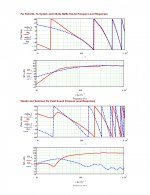
Below is a shot of what has me concerned. I can damp it out but it requires some fairly large values. I guess I'll just do it and maybe take some before and after distortion measurements.
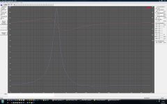
Looking closely at the second graph on the page you posted it almost looks like the impedance saddle you see from a vented enclosure with an Fb of ~600Hz.
Any thought on what is causing this?
You can see it much more subtly in my plot below except mine is centered at ~550Hz.
That saved me a lot of work. I was about to undertake similar measurements.
Below is a shot of what has me concerned. I can damp it out but it requires some fairly large values. I guess I'll just do it and maybe take some before and after distortion measurements.
Looking closely at the second graph on the page you posted it almost looks like the impedance saddle you see from a vented enclosure with an Fb of ~600Hz.
Any thought on what is causing this?
You can see it much more subtly in my plot below except mine is centered at ~550Hz.
Attachments
Looking closely at the second graph on the page you posted it almost looks like the impedance saddle you see from a vented enclosure with an Fb of ~600Hz.
You're welcome!
Well, doesn't a compression driver's low pass chamber + its short conically expanding throat + horn extension = a vented alignment? 😉
GM
I had a suspicion that's what I was seeing. Cool.
I'm still pretty new to all this horn loaded stuff.
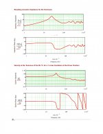
I have mocked up the n1500 crossover and am pretty impressed how it looks on the screen.
Next I'll pull out the mic and see what it thinks. I'll post some plots for anyone who is interested.
Below is the impedance of the n1500 with a zobel across the woofer. Even when expanded it looks good.
I'm still pretty new to all this horn loaded stuff.
I have mocked up the n1500 crossover and am pretty impressed how it looks on the screen.
Next I'll pull out the mic and see what it thinks. I'll post some plots for anyone who is interested.
Below is the impedance of the n1500 with a zobel across the woofer. Even when expanded it looks good.
Attachments
We're always interested! No such thing as too many measurement plots of Altec related designs.
This one's better overall, though designed for a later model, so may need a little tweaking: Altec Lansing 604-8H Phase-Correct Crossover with MF EQ
BTW, are you aware of the Altec Users forum? Altec User's Board
GM
This one's better overall, though designed for a later model, so may need a little tweaking: Altec Lansing 604-8H Phase-Correct Crossover with MF EQ
BTW, are you aware of the Altec Users forum? Altec User's Board
GM
I had completely forgotten about that forum.
Thanks for the tip.
I haven't had a lot of time to play with these drivers for a long while.
They have been with me for many, many, years. I seem to have misplaced the crossovers so I've decide to build some. No sense in re-inventing the wheel though.
Thanks for the tip.
I haven't had a lot of time to play with these drivers for a long while.
They have been with me for many, many, years. I seem to have misplaced the crossovers so I've decide to build some. No sense in re-inventing the wheel though.
- Home
- Loudspeakers
- Multi-Way
- Altec Lansing