just amazing topic ^^ I'm trying to make one,but in my country, I can not find some components @@
Mr. Mile,
I'm planning to upgrade my B500 to TEF, is this correct?
Regards,
It's correct, but in bias circuit use 1k2 instead 680R
Regards
It's correct, but in bias circuit use 1k2 instead 680R
Regards
Thanks...
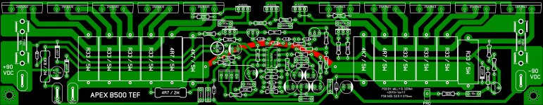
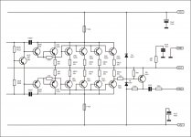
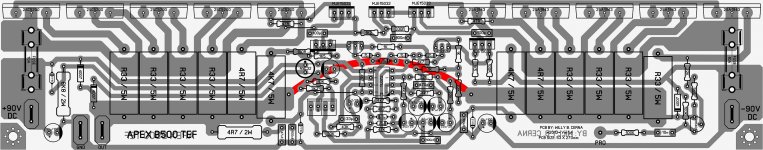
B500 4 pair Darlington output stage
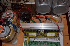
It's working....😀 very nice....
Thanks again Mr. Mile....
BTW what would be the max power could achieved with 4 pair of darlington output stage with +/-78VDC rail voltage?
Regards,
It's working....😀 very nice....
Thanks again Mr. Mile....
BTW what would be the max power could achieved with 4 pair of darlington output stage with +/-78VDC rail voltage?
Regards,
Attachments

It's working....😀 very nice....
Thanks again Mr. Mile....
BTW what would be the max power could achieved with 4 pair of darlington output stage with +/-78VDC rail voltage?
Regards,
Nice work, with +/-78VDC output will be about 50v RMS or 650W/4R.
Regards
congratulations
congratulations. excellent work. It's really impressive professional finish B-500 amp.
A query such heat sinks are computadpras.
PS: Please could you upload the pcb in Sprin Layout.
It's working....😀 very nice....
Thanks again Mr. Mile....
BTW what would be the max power could achieved with 4 pair of darlington output stage with +/-78VDC rail voltage?
Regards,
hai wiljj78,
may you share the design of the bottom side/cooper side?
thanks
best regard,
hai wiljj78,
may you share the design of the bottom side/cooper side?
thanks
best regard,
congratulations. excellent work. It's really impressive professional finish B-500 amp.
A query such heat sinks are computadpras.
PS: Please could you upload the pcb in Sprin Layout.
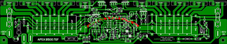
Thanks, here's the files.
Regards,
Attachments
nice
nice pcb again from wiljj78 🙂Thanks, here's the files.
Regards,
yes , working very nice
Hello LIEM POO...Greetings ..🙂 I have repositioned the tranies of this PCB to adopt to my Heat sink... Kindly check for any errors.
Hello Sir APEX... hope you can also give suggestion for the parts if something need to be improved. If all is well ... I can start making the PCB for this.
Many thanks to ALL
Best Regards
Attachments
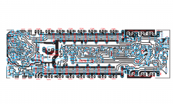
Thanks, here's the files.
Regards,
Hello WILJJ78... as usual very nicely done layout.. thanks for sharing...
Regards
Thanks, here's the files.
Regards,
Thank you wiljj78, nice design
best regard,
¿?
What power transistors you use in the end?: D
It's working....😀 very nice....
Thanks again Mr. Mile....
BTW what would be the max power could achieved with 4 pair of darlington output stage with +/-78VDC rail voltage?
Regards,
What power transistors you use in the end?: D
waiting for h900 tef pcb from woljj78 ,the kindes man
Thank you wiljj78 for sharing, i hope you don't mind to share H900 TEF like B500 TEF....
Getting ther soon....😉
What power transistors you use in the end?: D
I used all parts as stated on the drawings.
- Home
- Amplifiers
- Solid State
- 500W PA amplifier with Limiter