Hello Jaagut,
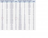
471 equates to 470pF, 471 and 470 are same thing, both 470pF, so this one's correct.
However, 33pF cap should have 33 printed on either side,
331 and 330 both equates to 330pF, so this one's incorrect.
Regards,
Aniket
471 equates to 470pF, 471 and 470 are same thing, both 470pF, so this one's correct.
However, 33pF cap should have 33 printed on either side,
331 and 330 both equates to 330pF, so this one's incorrect.
Regards,
Aniket
anybody who can confirm regarding capacitor codes to my previous post #2518? thanks in advance.
Attachments
Hello Jaagut,
471 equates to 470pF, 471 and 470 are same thing, both 470pF, so this one's correct.
However, 33pF cap should have 33 printed on either side,
331 and 330 both equates to 330pF, so this one's incorrect.
Regards,
Aniket
Big thanks Aniket!
If I found caps marked with 100 to 470, I would measure every one of them to ensure they are indeed <=47pF
pics of the testing.
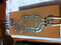
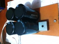
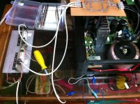
no hiccup during testing, no blown fuses, although some sparks occur in the PSU board due to loose contact in one of the capacitor pin, overall it is success. after confirmation that output DC offsets read 10mV, I connected the speaker and fed some music on the input signal.
my impression, the sound is pleasing, crisp and clear, better than my commercial amplifier in terms of sound quality.
i'm using 45-0-45Vac transformer temporarily from my existing commercial amp.
off to make additional channel for stereo mode.
many thanks apex for the good design of this amplifier! 😎
Attachments
pics of the testing.
no hiccup during testing, no blown fuses, although some sparks occur in the PSU board due to loose contact in one of the capacitor pin, overall it is success. after confirmation that output DC offsets read 10mV, I connected the speaker and fed some music on the input signal.
my impression, the sound is pleasing, crisp and clear, better than my commercial amplifier in terms of sound quality.
i'm using 45-0-45Vac transformer temporarily from my existing commercial amp.
off to make additional channel for stereo mode.
many thanks apex for the good design of this amplifier! 😎
Thank you for building B500, enjoy in good sound.
Regards
b 500
but I have a problem. plz tell me a suitable way to increase the gain. plz try to help me on this occasion to solve my problem .can you tell me how to bridge this amp.
apex sir i made this b500.it has a quality sound..i was wondered by hearing this sound..Thank you for building B500, enjoy in good sound.
Regards
but I have a problem. plz tell me a suitable way to increase the gain. plz try to help me on this occasion to solve my problem .can you tell me how to bridge this amp.
Good time sorry for my English. I have a problem with b500 at low volume and distortion are the large works perfectly, I'm not a big pro in Electronics but very much like the amp and the hunt to finish. I will be very grateful if someone can explain what could be the problem.
Gud day Sir apex i have transformer rated at 2kva output of 65-0-65 ac can i used this to b500? What is the maximum pairs of output trannies can i used, is it possible to use an 8pairs of c5200 and a1943 and any changes in values of parts in schematic.
Best Regards,
Nhor
Best Regards,
Nhor
Hi Apex and friends!
I have 2 channels of B500 connected to only one PSU. My torroidal transformer is giving output of 2x55vac to rectifier giving an output +/-80vdc rail voltage.
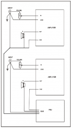
All grounds (input, output and speakers) of 2x B500 are connected to the PSU ground. Signal input of one B500 is connected to left signal source while the other is connected to right signal source. Although the 2x B500 is working, however the sound is not so clean because some noise or hum is present. How do I correct this problem?
Note: If I remove one of the B500, the other one performs a clean sound. No hum is present.
I have 2 channels of B500 connected to only one PSU. My torroidal transformer is giving output of 2x55vac to rectifier giving an output +/-80vdc rail voltage.
All grounds (input, output and speakers) of 2x B500 are connected to the PSU ground. Signal input of one B500 is connected to left signal source while the other is connected to right signal source. Although the 2x B500 is working, however the sound is not so clean because some noise or hum is present. How do I correct this problem?
Note: If I remove one of the B500, the other one performs a clean sound. No hum is present.
Hi Apex and friends!
I have 2 channels of B500 connected to only one PSU. My torroidal transformer is giving output of 2x55vac to rectifier giving an output +/-80vdc rail voltage.
All grounds (input, output and speakers) of 2x B500 are connected to the PSU ground. Signal input of one B500 is connected to left signal source while the other is connected to right signal source. Although the 2x B500 is working, however the sound is not so clean because some noise or hum is present. How do I correct this problem?
Note: If I remove one of the B500, the other one performs a clean sound. No hum is present.
a picture of your set-up helps...make sure your speaker ground return leads go direct to psu 0volt point abd not thru any pcb gound...
sir i very much interested in making this amp looking at its apparent simple design can u plz forward the construction details my email address robinsrakath at gmail dot com ........... if u have any pics of the amp it would be very helpfull and how r the sonics??. can i use any other op amp ic in the place of NE5532, (ie like TL072)
Last edited by a moderator:
a picture of your set-up helps...make sure your speaker ground return leads go direct to psu 0volt point abd not thru any pcb gound...
Attached illustrates how I set the ground wirings.
Attachments
Note: If I remove one of the B500, the other one performs a clean sound. No hum is present.
Try to disconnect the one without noise and see if the noise still exist on the suspected one, if the noise disappear while anyone of them is disconnected then there must be grounding issue somewhere.....
regards,
Last edited:
There's your mistake..........All grounds (input, output and speakers) of 2x B500 are connected to the PSU ground. ............. the sound is not so clean because some noise or hum is present. ...........
Never use the PSU Zero Volts as the Main Audio Ground (MAG).
Build a separate MAG with it's location optimised for good audio signal processing.
Bring a wire from the PSU Zero Volts to the MAG.
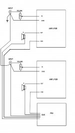
Attached illustrates how I set the ground wirings.
do not allow your signal ground share the same wire as your speaker ground wire, run them separate going to the 0 voltage(ground) point...
Use this ground wireing circuit.
Please enlighten me, what is the technical difference of using separate wires down to the PSU ground against bringing one single wire from PSU ground to a common single connection point where all ground wires meet? 😕
The charging current pulses in the transformer secondary circuit MUST NOT be allowed to contaminate any other signal return connection.
The easiset way to avoid that is to take a single wire from the PSU zero volts to the MAG.
The MAG MUST be located for best audio performance. That location is usually not at the PSU.
The easiset way to avoid that is to take a single wire from the PSU zero volts to the MAG.
The MAG MUST be located for best audio performance. That location is usually not at the PSU.
- Home
- Amplifiers
- Solid State
- 500W PA amplifier with Limiter