Hi there.
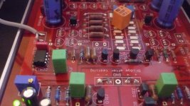
Finally I got the time to power up my paradise and do some measurements at our physics laboratory.
The pictures show the supply voltages (+/- 18V)without and within the caps for the distortion treatment.
the signal can be influenced by turning or tilting the pcb.
Though I think the signals are influenced by the enviroment. -No problem with the paradise.
Does anyone agree?
The supply is a simple one with only one Transformer.
Hi GandRalf,
this Looks like the amplifier is oscillating. Congratulations, this seems to be the second confirmed case (out of 670 boards, that is). Please check the assembly guide for how to fix that, there is a description in there. Hope that helps!
(why say sorry for €15K Agilent scope pictures)
Believe me. -It took a whole lesson for me, by the lab. ing., to use it. 😀
@ hesener:
Do I have to be pleased?Congratulations, this seems to be the second confirmed case
Yes I know that remedy to solve, but was unsure about the signallevel.
I thought this could be external interference. Cause the boards were not shielded and powered by a simple supply at the same time.
I will try to test each board at its own.
-If I get a new chance to use the lab...🙄
Just looking through my bag of bits, and there's a bundle of J109 in there. I know it was said they were no good in the psu, but are they fine on the other side or does a better replacement for the j310 exist?
...So besides the PSU J109 -> J113 replacement, is there any other changes that is recommended to do?
I read somewhere about J107 replacement, is that something to look at or is it perfectly fine as it is?
I haven't started building, since i'm working on other projects - but i'm going to order components so i'll have them ready when i start...
I read somewhere about J107 replacement, is that something to look at or is it perfectly fine as it is?
I haven't started building, since i'm working on other projects - but i'm going to order components so i'll have them ready when i start...
Believe me. -It took a whole lesson for me, by the lab. ing., to use it. 😀
@ hesener:
Do I have to be pleased?
sorry it was meant as a joke. If the noise is a few MHz, it's the Shunts; if it is 70MHZ and higher, it's the amplifier... At least I have seen no Variation from that pattern yet.....
let us know the outcome!
transistor swaps:
I've just matched my most recent batch and could do with some swaps.
I need...
327's in the range 430-450
337's in the range 410-430
Please let me know what you have and need i have lots of 327 in the 395-405 range
I've just matched my most recent batch and could do with some swaps.
I need...
327's in the range 430-450
337's in the range 410-430
Please let me know what you have and need i have lots of 327 in the 395-405 range
sorry it was meant as a joke.
So was my reply.😉
Sorry for that. That`s the problem if we try to do ironic in a not native language.
Should have used a smilie then...🙄

transistor swaps:
I've just matched my most recent batch and could do with some swaps.
I need...
327's in the range 430-450
337's in the range 410-430
Please let me know what you have and need i have lots of 327 in the 395-405 range
PM sent
I am replacing the gb 109 with the 113 as FdW suggested.
Please advise what resistor values need to be altered to accommodate this 113?
Thanks in advance, the more specific the better, if you could use the # system that was created for assembly that would be great!
(Back from holyday) Use a 1K Rgs resistor.
Just looking through my bag of bits, and there's a bundle of J109 in there. I know it was said they were no good in the psu, but are they fine on the other side or does a better replacement for the j310 exist?
(Back from holyday) The PSU JFets should be J113 and the Rgs for these is 1K (replace the 3.3K resitors)
Thanks FdW.(Back from holyday) The PSU JFets should be J113 and the Rgs for these is 1K (replace the 3.3K resitors)
There are two 3k3 resistors per board, they sit just outside of the 107/207 fet position on the numbered schematic. Just wanted to verify? If this is correct perhaps this could make it to the build guide too?
On my PCBs they are between the transistor marked J310 and the 1uF capacitor, closed to the exit of the shunt.
I purchased a bunch of 2sk170 from Zhoufhang on ebay, I only need 6 of them so there are 3 sets of 6 up for grabs. First pm's get them
These transistors have driven me mad over the course of two builds. I've had awful matches, with little overlap between 327 and 337. Then yesterday i get 100 337 from farnell and more than 50% of them measure between 390 and 420 for Hfe.
So I now have the input stage matched with identical values across both channels, not 1% or 5% but the exact same values. Every other 327 and 337 on both channels is matched within 1%.
Crazy..
I must say I'm quite excited to power this up and measure it to see if it is any different to my 5% build.
So I now have the input stage matched with identical values across both channels, not 1% or 5% but the exact same values. Every other 327 and 337 on both channels is matched within 1%.
Crazy..
I must say I'm quite excited to power this up and measure it to see if it is any different to my 5% build.
- Home
- Source & Line
- Analogue Source
- Paradise Builders