Yaqin SD-CD3 Tube Buffer
Hi all!
Do you must give informed schematic for this tube buffer: Yaqin SD-CD3 Tube Buffer?🙁
Thank you and cheers!
Hi all!
Do you must give informed schematic for this tube buffer: Yaqin SD-CD3 Tube Buffer?🙁
Thank you and cheers!
Where is the schematic?😕Hi all!
Do you must give informed schematic for this tube buffer: Yaqin SD-CD3 Tube Buffer?🙁
Thank you and cheers!
thank you!
Oh yes, that's it .... instead of 6n8 schematic to put 6n1p-EV?posting #94? What do you mean? Schematic with notes on voltage readings?
What should be the anode voltage + B =?
thank you and cheers!
Socket adapter
Is not a 6n1p a 9-pin tube and the CD3 is wired with 8-pin sockets? You would have to replace the sockets or acquire/make 9 -> 8 pin socket adapters which are somewhat costly.
Two New Tube Adaptor ECC85 6N1P 6H1N to 6SN7 or 6N2P to 6SL7 Free Shipping World | eBay
Why not put in two premium name-brand 6SN7 or 6SN7GT? Done, 2 minutes!
Oh yes, that's it .... instead of 6n8 schematic to put 6n1p-EV?
What should be the anode voltage + B =?
thank you and cheers!
Is not a 6n1p a 9-pin tube and the CD3 is wired with 8-pin sockets? You would have to replace the sockets or acquire/make 9 -> 8 pin socket adapters which are somewhat costly.
Two New Tube Adaptor ECC85 6N1P 6H1N to 6SN7 or 6N2P to 6SL7 Free Shipping World | eBay
Why not put in two premium name-brand 6SN7 or 6SN7GT? Done, 2 minutes!
Hi Konga!Took off the tube guard and swapped in a pair of NOS RCA 6F8G tubes on adapters.
An externally hosted image should be here but it was not working when we last tested it.
An externally hosted image should be here but it was not working when we last tested it.
Where a schematic of this beaut??😕
thank you!
I'll put 6N7GT, it the sound gives ? We need some changes in the schematic?Is not a 6n1p a 9-pin tube and the CD3 is wired with 8-pin sockets? You would have to replace the sockets or acquire/make 9 -> 8 pin socket adapters which are somewhat costly.
Two New Tube Adaptor ECC85 6N1P 6H1N to 6SN7 or 6N2P to 6SL7 Free Shipping World | eBay
Why not put in two premium name-brand 6SN7 or 6SN7GT? Done, 2 minutes!
thank you
S
This is I think the second or third time you have left out the "S" 😱
6n7GT would be a different tube that exists but is probably wired differently.
You WANT a 6SN7 or 6SN7GT or maybe 6SN7GTB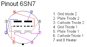 317 × 173 - en.wikipedia.org
There seems to be a good commentary on 6SN7 variants here:
https://www.tubeworld.com/6sn7.htm
There are some comments below about another more extreme MOD idea involving the 7193 single triode tube a MOD I may eventually DO:
AudiogoN Forums: Preamp Deal of the Century
More commentary about 7193 conversion:
6SN7GT vs 12au7 [Archive] - AudioKarma.org Home Audio Stereo Discussion Forums
I'll put 6N7GT, it the sound gives ? We need some changes in the schematic?
thank you
This is I think the second or third time you have left out the "S" 😱
6n7GT would be a different tube that exists but is probably wired differently.
You WANT a 6SN7 or 6SN7GT or maybe 6SN7GTB
 317 × 173 - en.wikipedia.org
There seems to be a good commentary on 6SN7 variants here:
https://www.tubeworld.com/6sn7.htm
There are some comments below about another more extreme MOD idea involving the 7193 single triode tube a MOD I may eventually DO:
AudiogoN Forums: Preamp Deal of the Century
More commentary about 7193 conversion:
6SN7GT vs 12au7 [Archive] - AudioKarma.org Home Audio Stereo Discussion Forums
This is I think the second or third time you have left out the "S" 😱
6n7GT would be a different tube that exists but is probably wired differently.
Unless his line of questioning changes, I wouldn't give Gost22 the time of day...
The 6F8G upgrade is also easy, and as the pictures show, very elegant. Yes, rewiring or adapters. GOST22 you must evaluate the spec sheets of the stock original tubes and compare them to any tube spec sheets you wish to us as alternatives. Pin layouts too!! I would NOT expect miracles.
Hey guys, how are you all? I have been reading this thread with much interest, I just got one of these baby's and am looking to change the capacitors, BUT...
I've never done this before, I am going to learn how to solder first, then buy the capacitors, but I need help.
1) What wattage should the soldering iron be?
2) Do I need to buy a multimeter, and why and how do they work?
3) Does anyone know what the size of the blue caps are in the tube buffer so I can get correct size ones to replace them?
If I have missed anything out, or if there is anything I should know about changing caps, please let me know, I'm just a novice.
thanks
Last edited:
Sorry to be boring, but my advice is "don't do it". The risk of damage is quite high if this will be your first soldering job, and the most likely outcome is no change at all in the performance of the unit. The second most likely outcome is that you break something, and then have insufficient knowledge to fix it.tazzo said:If I have missed anything out, or if there is anything I should know about changing caps, please let me know, I'm just a novice.
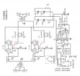
There is a circuit diagram in this thread (I forget where). That will tell you the value of the caps.
Well, I'm going to learn to solder first, as for performance in the unit, users on this thread seem to say otherwise.
Hello again. Hope you like the schematic.
I'm not a tech, though I've built some kits in my time. I'd appreciate some observations and corrections from the techs in residence.
First, judging from the schematic I've submitted, I'd say that all the capacitors and the 680 & 100K resistors are in the signal path. I concluded that the 20K resistor is not. I'd appreciate any corrections.
Second, in the interest of properly orienting any capacitor upgrades, could someone point out the source and destination or ground sides of the capacitor positions judging from the supplied schematic?
Third, a very vexing issue. There's no damn difference whether my unit is on or off. That is, the system continues to play music when I shut off power to the Yaquin. There's no sonic difference whether on or off. When the unit is turned on, it's 'instant on' with no tube warm up, or turn-on thumps, and likewise when I turn the Yaquin off, there is no shut-down thump and the music continues to play merrily along.
Is it plausible that this unit acts as a 'straight wire' connection when powered down? Or have we been scammed? It just seems improbable that an active circuit would behave like this.
My connection scheme is DAC > Yaquin buffer > passive stepped attenuator > amp.
Any help is more than appreciated.
See post #113!!😉
Well, I'm going to learn to solder first, as for performance in the unit, users on this thread seem to say otherwise.
Good idea, and these types of lessons are best learned from someone locally; not online. Electronics are fun and a good opportunity to learn, but can be very dangerous if you don't know what to do.
Hey, I got the work done, just running it in now. Has anyone tried using these little things as mono blocks, using a Y 2 to 1 RCA male splitter and an integrated amp as a pre-amp?
Would it be safe using two? I might try that...
Would it be safe using two? I might try that...
I don't understand your question, but a buffer cannot be used as s monoblock or any amplifier as it provides no gain by design.
Mono-Block question cont'd
the tubes used in this buffer are dual triodes, and each tube has those triodes wired in parallel in the circuit, so, in a way you are already getting both segments of each tube, per-channel. If you found a way to mono-block as you say, I doubt you would hear anything much different. Now, it is more likely that sonics could be impacted/changed some by tube swapping, or modding to take the various other options like 6F8G, {or if I had a CD3, maybe the 7193}. Or just try better 6SN7s. 6n16b-v might be a simple experiment, solder some leads to a pair, or use socket-savers to adapt them.
I don't understand your question, but a buffer cannot be used as s monoblock or any amplifier as it provides no gain by design.
the tubes used in this buffer are dual triodes, and each tube has those triodes wired in parallel in the circuit, so, in a way you are already getting both segments of each tube, per-channel. If you found a way to mono-block as you say, I doubt you would hear anything much different. Now, it is more likely that sonics could be impacted/changed some by tube swapping, or modding to take the various other options like 6F8G, {or if I had a CD3, maybe the 7193}. Or just try better 6SN7s. 6n16b-v might be a simple experiment, solder some leads to a pair, or use socket-savers to adapt them.
- Home
- Source & Line
- Analog Line Level
- Yaqin SD-CD3 Tube Buffer - upgrading caps