The 6J1 is the Chinese version of the 6AK5/EF95 UHF pentode. An odd choice for audio, as its excellent RF properties are likely to make it difficult to keep stable. The ECC88 is completely different (twin triode) and would require a redesign of the circuit.
Yes, wrong number of pins, CD2 or CD3 [either] would require adapters 9P? female to rewired 7P in the CD2? Something that might be much easier to try is 6n16b-v tubes since they have the wire leads {with sleeve tubing added}, or you could tack tube-pins on the the wires and stuff in socket with needle-nosed pliers...or tack leads to 14Ga house wire "pins"? 16Ga? Parallel the two triodes in each tube -- same way they do in CD3
Looks as attaching the wire make sense to me. I'm not really technical, can you please have a look at the pins picture of ECC88 and point as to what pins on it need to be joint together for the purpose of inserting this wires into the 6 Pins ( holes) available. If it becomes too difficult may be I can remove 6 Pin sockets and solder 9 Pin socket in its place all-together.
PS. would it be save to solder copper wires to the pins on the Valve?
Soldering to valve pins is almost certain to crack the glass.
Why on earth do you want to use the wrong valve for the circuit?
Why on earth do you want to use the wrong valve for the circuit?
7-9 pin
CD2 takes 7-pin tubes, easiest but costly is make a socket-adapter for each tube.
9P female to 7P male. Well, easiest is acquire 2x Mullard CV4010 and you are DONE. Very well-reviewed tubes! IMHO. If you are going to fool around cross-wiring with no sockets, I would think the 6N16b-v tubes would be the best place to start. Find the heater pins, that one's easy. Beyond that just parallel the Anode-anode, cathode-cathode, grid-grid... Maybe I am forgetting but I tthink that's it, 5 pins actually USED. 6n16b-v, or JAN 6021W would both be fun to test. Socket adapters will not be fun. Sure you could pull out the 7-pin sockets and replace with 9P BUT the 9P will be bigger diameter, LOTS of work vs dropping in CV4010 or playing with wire-leaded tubes and some optional solid wire [wire leads could be doubled up//folded and made stiff with solder?] Cd3 also parallels dual triodes into singles.
Looks as attaching the wire make sense to me. I'm not really technical, can you please have a look at the pins picture of ECC88 and point as to what pins on it need to be joint together for the purpose of inserting this wires into the 6 Pins ( holes) available. If it becomes too difficult may be I can remove 6 Pin sockets and solder 9 Pin socket in its place all-together.
PS. would it be save to solder copper wires to the pins on the Valve?
CD2 takes 7-pin tubes, easiest but costly is make a socket-adapter for each tube.
9P female to 7P male. Well, easiest is acquire 2x Mullard CV4010 and you are DONE. Very well-reviewed tubes! IMHO. If you are going to fool around cross-wiring with no sockets, I would think the 6N16b-v tubes would be the best place to start. Find the heater pins, that one's easy. Beyond that just parallel the Anode-anode, cathode-cathode, grid-grid... Maybe I am forgetting but I tthink that's it, 5 pins actually USED. 6n16b-v, or JAN 6021W would both be fun to test. Socket adapters will not be fun. Sure you could pull out the 7-pin sockets and replace with 9P BUT the 9P will be bigger diameter, LOTS of work vs dropping in CV4010 or playing with wire-leaded tubes and some optional solid wire [wire leads could be doubled up//folded and made stiff with solder?] Cd3 also parallels dual triodes into singles.
Soldering to valve pins is almost certain to crack the glass.
Why on earth do you want to use the wrong valve for the circuit?
I thought while I already have a quality valve, I may just find a way to use them. As I understand it should be possible by re-soldering and changing valve sockets, unless the valve (9 pine one) is not suitable by internal parts requirements would you think that could be the case?
Cathode follower
Cathode follower circuit is not as much intended to change dynamics drastically, it is basically an impedance match high to lower with unity-gain or less? People roll tubes in anything they CAN, but do not expect miracles. I suspect socket-adapters would cost you at least $15-20USD each? [Just a guess]. A pair of CV4010 might be less than that, and wire-lead tubes also very cheap. For that matter a wire leaded single pentode could be forced to work in Triode mode in CD2 7P sockets, not that I would try that first. Watch your plate voltage ratings on the little tubes if get into that. CD2 or CD3 is one more thing in the path... also try playing WITHOUT {shhhhh}
Mistake: cannot use any tubes with directly heated cathodes in the CD2 or CD3, so cheap wire-leaded Pentodes might be OUT, as it would have directly heated cathode = no workie.
I thought while I already have a quality valve, I may just find a way to use them. As I understand it should be possible by re-soldering and changing valve sockets, unless the valve (9 pine one) is not suitable by internal parts requirements would you think that could be the case?
Cathode follower circuit is not as much intended to change dynamics drastically, it is basically an impedance match high to lower with unity-gain or less? People roll tubes in anything they CAN, but do not expect miracles. I suspect socket-adapters would cost you at least $15-20USD each? [Just a guess]. A pair of CV4010 might be less than that, and wire-lead tubes also very cheap. For that matter a wire leaded single pentode could be forced to work in Triode mode in CD2 7P sockets, not that I would try that first. Watch your plate voltage ratings on the little tubes if get into that. CD2 or CD3 is one more thing in the path... also try playing WITHOUT {shhhhh}
Mistake: cannot use any tubes with directly heated cathodes in the CD2 or CD3, so cheap wire-leaded Pentodes might be OUT, as it would have directly heated cathode = no workie.
Last edited:
I recently picked up the Grant Fidelity B283 MKII which is about the same as the Yaqin CD-3. Swapped out stock tubes for a matched pair of 1952 Raytheon 6SN7, and the buffer sounds good. I'm using it between my passive preamp and my powered Martin Logan Purity speakers to help the impedance mismatch, and the combo is great.
My next step is upgrading the 0.47uF and 0.22uF caps, but I can't find the correct value caps I want for the two 0.22uF caps. Can I swap in something larger like .56uF? I am not looking for any gains or improvements, just want something that will work and not cause any issues.
Thanks!
My next step is upgrading the 0.47uF and 0.22uF caps, but I can't find the correct value caps I want for the two 0.22uF caps. Can I swap in something larger like .56uF? I am not looking for any gains or improvements, just want something that will work and not cause any issues.
Thanks!
Attachments
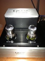
Grant Fidelity B283 MKII
a fellow in another thread would have some advice for you:
http://www.diyaudio.com/forums/chip-amps/228620-alittle-disaster-story.html
The stock caps might not be so bad, you might consider adding in maybe some smaller teflon or PIO "bypass" caps in parallel with the main INs and OUTs, some bleeder Rs, and if you can find any photoflash caps that can handle the high voltage your unit runs at, those might be a welcome addition to the PSU for little cost. I have been known to switch to faster diodes in the bridge too,
UF4007.
I recently picked up the Grant Fidelity B283 MKII which is about the same as the Yaqin CD-3. Swapped out stock tubes for a matched pair of 1952 Raytheon 6SN7, and the buffer sounds good. I'm using it between my passive preamp and my powered Martin Logan Purity speakers to help the impedance mismatch, and the combo is great.
My next step is upgrading the 0.47uF and 0.22uF caps, but I can't find the correct value caps I want for the two 0.22uF caps. Can I swap in something larger like .56uF? I am not looking for any gains or improvements, just want something that will work and not cause any issues.
Thanks!
a fellow in another thread would have some advice for you:
http://www.diyaudio.com/forums/chip-amps/228620-alittle-disaster-story.html
The stock caps might not be so bad, you might consider adding in maybe some smaller teflon or PIO "bypass" caps in parallel with the main INs and OUTs, some bleeder Rs, and if you can find any photoflash caps that can handle the high voltage your unit runs at, those might be a welcome addition to the PSU for little cost. I have been known to switch to faster diodes in the bridge too,
UF4007.
Attachments
One more thing I would be tempted to try is the 7193 aka 2c22 tubes though that project would require some serious work.
Explain the different sound between Octal and 9 pin tube preamps - Page 3 - AudioKarma.org Home Audio Stereo Discussion Forums
AudiogoN Forums: Preamp Deal of the Century
Explain the different sound between Octal and 9 pin tube preamps - Page 3 - AudioKarma.org Home Audio Stereo Discussion Forums
AudiogoN Forums: Preamp Deal of the Century
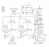
After reading that post, I installed some bleeder resistors on the inputs and outputs as outline below in green. I also installed some bleeder resistors on the power supply caps as I measured them at 25v after being off for 24 hours. Now, once off and unplugged, the circuit retains zero voltage, and the additions were the easiest mods I've done in quite a while; as you can guess.
An externally hosted image should be here but it was not working when we last tested it.
I have my six ANSAR PPA caps to replace the blue-jobbies, but haven't been able to get the board out of the chassis. After I removed all connections, the front and back panels, the four stand-off screws on the top (bottom of chassis), and two stand-off screws on the bottom of the board (top side of the chassis), the board still can't be removed. I've narrowed down the issue to the stand-offs on the board which don't allow me pull the board up on down, and the tube sockets which don't allow me to slide it forward or back. I assumed the best option was to remove the stand-offs, but wasn't able to unscrew them in the few minutes I had last night.
What was your best practice for those who have successfully upgraded their caps?
What was your best practice for those who have successfully upgraded their caps?
Nevermind. 🙂 I was able to slide the board out far enough to find out that there no pads on the back of the board. The only pads are on the side you can see/access, so let the soldering begin!
Changes in schematics with tube 6n8
Hi guys!
Can I the schematics with 6n8 replace with tube 6n8s or 6n7GT or necessary (needed) some changes?
(Normally replaceable-slightly different:6n8p)
Thank you and cheers!
Hi guys!
Can I the schematics with 6n8 replace with tube 6n8s or 6n7GT or necessary (needed) some changes?
(Normally replaceable-slightly different:6n8p)
Thank you and cheers!
Last edited:
Hi folks:
Just bought the CD3 buffer and have access to the schematic, which I thought you boys would like. But I have a vexing issue and some observations to follow in my next message.
Hi,
How much is the voltage on anode (V1 =?)😕.
Can be replace 6n8p with tube 6n7GT(Russian)?🙁
thank you!
Attachments

Last edited:
Not wired the same. You can make conversion sockets, or, you could try 6n16b-V soldered to a conversion socket, or to little pieces of stiff wire? [you need to know what you are doing for sure]. 6SN7 easier.
Since the Conrad.com at the sale tube 6n7GT duble triode Octal base 8-pin for 16.21Euro !Why not just use a widely available and well built 6SN7?
My Grant Fidelity B283 MKII with freshly upgraded ANSAR PPA capacitors, bleeder resistors on PS caps and inputs and outputs, plus film bypass caps on PS caps. The sound already has more texture and body, and that was just while watching TV. I'll put some hours on them tomorrow and do a little critical listening with some of my favorite music to get a better idea of what aural gains were made.
The install was actually very easy after I figured out the that bottom side of the circuit board (the side you don't see), does not have any pads on it. All the soldering is done on the top side, so just trim the cap leads to fit, make sure they don't do too far through the holes, and solder in place. The four ANSAR 0.47uF caps barely fit together in the provided space, and the thick lead (same as ClarityCaps in my experience) BARELY fit through the holes in the board. It was a tight fit, but everything was installed cleanly, and looks great!
The install was actually very easy after I figured out the that bottom side of the circuit board (the side you don't see), does not have any pads on it. All the soldering is done on the top side, so just trim the cap leads to fit, make sure they don't do too far through the holes, and solder in place. The four ANSAR 0.47uF caps barely fit together in the provided space, and the thick lead (same as ClarityCaps in my experience) BARELY fit through the holes in the board. It was a tight fit, but everything was installed cleanly, and looks great!
An externally hosted image should be here but it was not working when we last tested it.
COnrad 130432 - 62 *is* a 6SN7GT seems actually costly to me to "upgrade" a cathode follower with a no-name tube which might even be a 6n8__
The stock caps might not be so bad, you might consider adding in maybe some smaller teflon or PIO "bypass" caps in parallel with the main INs and OUTs, some bleeder Rs, and if you can find any photoflash caps that can handle the high voltage your unit runs at, those might be a welcome addition to the PSU for little cost. I have been known to switch to faster diodes in the bridge too,
UF4007.
After changing the original coupling caps with numerous film caps, I'd say
1) I'd agree the stock caps are OK. To better them costs quite a few pennies.
2) IMO the sonics of the coupling caps has as much impact as the sonic quality of the 6sn7's.
In the end, I stayed with original AuriCaps on the inputs - which I think is an excellent value,
but are quite transparent.
For the output coupling caps, I used Mundorf M Cap Supremes.
But would like to try the new Mundorf EVO silver/gold oil caps.
Please note that even though film caps are "Non Polarized", the outside
of the foil should be used as a shield - which means it should be connected
to the low Z side of the circuit.
As for changing the diodes, the CD3 is dead silent, so is noise on the +Ve rail an issue ?
As for signal tubes, I'm a huge fan of vintage Amperex and Siemens
however, within the 6sn7 family, the best tube I've ever heard
are Shuguang Treasure CV-181z's.
.
Last edited:
- Home
- Source & Line
- Analog Line Level
- Yaqin SD-CD3 Tube Buffer - upgrading caps