Well I would gladly see an ADC replacement in the qa400.
Proprietary software if it's not bugged is not that bad...
Btw anyone knows or has used one of the Aaronia spectran devices?
Proprietary software if it's not bugged is not that bad...
Btw anyone knows or has used one of the Aaronia spectran devices?
I have tried 7-8 of the semipro cards and the RME and they all have problems. The ESI Juli@ seems to have the most benign interface and give the most consistent results. But its noise floor is not what it should be. I use it with the demo boards to get what I want. And you have a desktop computer on the back side. I can see making a replacement analog module for the ESI but a portable solution would be really great.
I posted some measurements showing what is possible with the AK5394A.
I posted some measurements showing what is possible with the AK5394A.
Well I would gladly see an ADC replacement in the qa400.
Proprietary software if it's not bugged is not that bad...
Btw anyone knows or has used one of the Aaronia spectran devices?
Not so simple to do. They used a codec.
I would not mind playing with one. just have no interest in spending more money on this stuff.
I looked into it. It seems to need drivers and run on an Atmel AVR32. The AudioWidget runs on an AVR32 and is fully UAC2 compliant. I'm pushing for a Digital input. Hopefully soon.
I looked into it. It seems to need drivers and run on an Atmel AVR32. The AudioWidget runs on an AVR32 and is fully UAC2 compliant. I'm pushing for a Digital input. Hopefully soon.
I have arrived at R values to scale 0dB to the FS of the AK4385B.
The ADC FS is 2.9Vpp differential.
I give some details of performing the mod in another post.
Here are some schematics and results.
The first sch is the original. The second sch is the AKM recommended and the third sch is the mod.
The rest is self explanatory.
Cheers,
Hi David;
I notice that in the first schematic where you say it is the original; the op amps are all OPA-827s and the final is JRC2068s. I realized that there has been some gain scaling but did you also swap out the op amps?
Just curious.
Thanks
Matt
Hi David;
I notice that in the first schematic where you say it is the original; the op amps are all OPA-827s and the final is JRC2068s. I realized that there has been some gain scaling but did you also swap out the op amps?
Just curious.
Thanks
Matt
Hi Matt,
No I didn't swap op amps. I just gabbed something from the symbol lib to use for the schematic. Next time I use the generic op amp to avoid confusion.
I see no need to change the op amps. The results are good as they are.
Tracker Pre on Windows XP SP3 runs at up to 192 kHz fine for me for years.
/S
/S
Other notes (before I forget). The Tracker pre only runs at 44.1 and 48 on XP (at least with the drivers from EMU on their site). It runs up to 192 on Win 7. The 0404 does run up to 192 on XP. On Win 7 to get the input sensitivity down I need to set the gain in the windows mixer to 5 on the input. I still get occasional glitches at 192 with the EMU stuff.
I'll post a picture of the Tracker insides later this week.
Strange, people on thos board have measured the EMU1212m with much better results. See attachments.
/S
/S
I've got the EMU1212 up and running but I've got to say I'm pretty disappointed.
I think this is a waist of a AK5394A. Just my opinion though. It took me over half an hour to get ARTA calibrated with this thing. It won't work with out the application that goes with it and that really get's in the way of third party apps.
See for yourself. This is no good for high resolution measurement and is another reason we are doing the Capture Widget project.
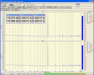
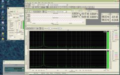
The first pic is self explanatory and the second is with a 75 ohm load on the input.
Attachments
Tracker Pre
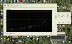
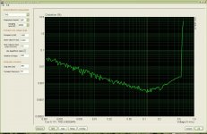
Here are a few of my own Tracker Pre measurements in loop back I did in 2011. Both with 48k and 192k. 48k gives lowest THD. 192k is only for testing.
Still not good enough.
/S
Here are a few of my own Tracker Pre measurements in loop back I did in 2011. Both with 48k and 192k. 48k gives lowest THD. 192k is only for testing.
Still not good enough.
/S
Attachments
Have you tried to paralleling ADC's for better performance? Either mulit-channel products or with the IC themselves.
Thx-RNMarsh
Thx-RNMarsh
where is the How To part??
Hi dave... where is the mod description - the how too - pictures etc for the 0204? I see the schematics here but where did you place the How to part of it??
Thx
RNMarsh
Hi dave... where is the mod description - the how too - pictures etc for the 0204? I see the schematics here but where did you place the How to part of it??
Thx
RNMarsh
Hi dave... where is the mod description - the how too - pictures etc for the 0204? I see the schematics here but where did you place the How to part of it??
Thx
RNMarsh
My camera crapped out so I can't take pics. You should be able to figure it out once you have the EMU0204 lid off. The part designator numbers for the EMU board are on the schematic. The op amps are dual standard pin out. I removed the pot on the from panel to open that part of the circuit. You'll need a magnifying glass. Glasses if you where them.
Cheers,
Rats! yes, I have a mag-glass. Thanks... I'll look at the schematic for the board numbers... didnt realize that's what they were. Just getting around to it. Thx - Richard
I've been looking all around with a magnifying eye piece... have not found all of them, yet. I think I'll just take a picture of the board and put it on my large PC screen and zoom in on it there.
-Richard
-Richard
I've been looking all around with a magnifying eye piece... have not found all of them, yet. I think I'll just take a picture of the board and put it on my large PC screen and zoom in on it there.
-Richard
Looking at the board from the front of the 0204, R53 is about half an inch left of U5.
With the pot for the right channel removed connect a 3k or 3.2k resistor from pin 7 to pin 2 of U5.
I think there was a 100 ohm resistor I had to remove beside the phone jack. I take a look and let you know.
That really about it.
I remember now. Remove R26 and solder a wire to the nearest ground and the non inverting pin 5 of U5. There is a ground on the board used for a test point just to the right and slightly below U5. Square pad. If you like you can leave R26 in but it has to be routed to ground. It was the non inverting input for the original configuration. R26 must be removed from the input jack. I found it easier to just remove it altogether.
Last edited:
I looked for an hour... no R26. Did you mean R29 instead?
Or, give me a clue to where R26 is... near which IC? or other landmark.
-RM
Or, give me a clue to where R26 is... near which IC? or other landmark.
-RM
I looked for an hour... no R26. Did you mean R29 instead?
Or, give me a clue to where R26 is... near which IC? or other landmark.
-RM
Hi Rick,
The are two resistors on the left side of the 'right' input jack.
Take your multimeter and trace the one that connects to the jack on one side and U5 pin 5 on the other side. That's the resistor.
Thanks -- as you can tell, i am unlikely to redo from scratch what others already did without details... too time consuming. Too many projects and trying to sell a house as well. So, i'll get back to this mod when i have more time. meanwhile, i'll try the eMu-0404 that i did a mod and use ARTA with it. I want to see if either e-Mu model is better than the QA400 in accuracy at low distortion levels.
Thx-RNMarsh
Thx-RNMarsh
Thanks -- as you can tell, i am unlikely to redo from scratch what others already did without details... too time consuming. Too many projects and trying to sell a house as well. So, i'll get back to this mod when i have more time. meanwhile, i'll try the eMu-0404 that i did a mod and use ARTA with it. I want to see if either e-Mu model is better than the QA400 in accuracy at low distortion levels.
Thx-RNMarsh
Just the front panel gain adjustment and cal I described in the PM and you'll get good results.
- Status
- Not open for further replies.
- Home
- Design & Build
- Equipment & Tools
- EMU0204 mods for FFT measurements