Hey thanks for that, what a cracking new toy.
What do you make of the signal current in the V1 (17v) supply though – should that be there d'you think?
Don't quite follow what you mean 🙂
The supply is "perfect" in that it maintains 17 volts. The current drawn by the amp varies as the output voltage varies (and hence current in the load varies). This is reflected in the current drawn from the 17 volt rail.
The current drawn by the amp varies as the output voltage varies ...
Yes, indeed it does seem to – but JLH thought it didn't and he says so in several places, it's why he specified a simple PSU. I thought that was interesting and I'd certainly like to know about it before attempting a build.
Yes, indeed it does seem to – but JLH thought it didn't and he says so in several places, it's why he specified a simple PSU. I thought that was interesting and I'd certainly like to know about it before attempting a build.
Let me think about that for a few minutes... I want to try something in the simulation.
I wanted to prove to myself what was going on. I think you mean that because it a Class A amp and not push pull the current draw should be constant.
If the top transistor is replaced with a current source the supply current is essentially steady. I also modified the amp to use a simple resistor load and that to gives the large supply current variation of the original design. It also varies just as much with no load.
I'll post some pics...
If the top transistor is replaced with a current source the supply current is essentially steady. I also modified the amp to use a simple resistor load and that to gives the large supply current variation of the original design. It also varies just as much with no load.
I'll post some pics...
It also varies just as much with no load.
Scrub that bit 😀 That's me tying myself in knots.
where the load is parallel to the output current modulating device then it is possible to create a constant current ClassA amplifier.
The JLH does have this parallel requirement. But the JLH does not use a CCS as the collector load. The CCS is a modulated type and thus the constant ClassA current draw does not apply.
There are VERY FEW ClassA topologies that have constant current draw.
The JLH does have this parallel requirement. But the JLH does not use a CCS as the collector load. The CCS is a modulated type and thus the constant ClassA current draw does not apply.
There are VERY FEW ClassA topologies that have constant current draw.
where the load is parallel to the output current modulating device then it is possible to create a constant current ClassA amplifier.
The JLH does have this parallel requirement. But the JLH does not use a CCS as the collector load. The CCS is a modulated type and thus the constant ClassA current draw does not apply.
There are VERY FEW ClassA topologies that have constant current draw.
That seems to be right Andrew. I'll have to dig the original articles out sometime to see how JLH described the current draw on the PSU.
I'll have to dig the original articles out sometime to see how JLH described the current draw on the PSU.
Here's a good source of JLH PDFs: The Class-A Amplifier Site Let's know what you find.
I wasn't looking for supply modulation, I was trying to work out why it had such an odd efficiency (~32%) and realised the PSU must be implicated - that's when I spotted your LTspice post so thanks again for that.
Thanks for the link. I knew the old site had vanished and couldn't remember where it had moved to.
Just quickly reading through some of the articles reminded me of the controversy there was over its operation...no one was quite sure and it varied depending on whether the devices were matched or whether the higher gain device was at the top or bottom.
As to the efficiency. Well Class A that has a constant current source is around 25% efficient and push pull around 50%. If JLH is around 33% (and I don't know if that is the figure) then I guess that implies its a half way house between the two 😀
That's not much of an answer is it 🙂
I would take the PSU as a different topic altogether. If you consider the efficiency of the amp as a whole including whatever PSU you use then it could vary enormously. You could have a super efficient SMPS powering it or a linear supply with series regs and large in/out overhead. The efficiency of the amp is separate though.
It's because of the 2N3055's non-linear current gain. The peak output current is less than double the quiescent current, so you have to set the quiescent current higher than half the peak output current.As to the efficiency. Well Class A that has a constant current source is around 25% efficient and push pull around 50%. If JLH is around 33% (and I don't know if that is the figure) then I guess that implies its a half way house between the two 😀
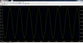
It's interesting to look at the collector currents of the two output devices in a sim, with fairly high output power.
Using output devices with constant (and equal) current gain, you'd get closer to the ideal 50%.
It's because of the 2N3055's non-linear current gain. The peak output current is less than double the quiescent current, so you have to set the quiescent current higher than half the peak output current.
It's interesting to look at the collector currents of the two output devices in a sim, with fairly high output power.
Using output devices with constant (and equal) current gain, you'd get closer to the ideal 50%.
Indeed. In the file I posted some while back if you set the input voltage to 0.6 volts and first change just the top transistor to the standard library model 2N3055 and then do the same again for just the bottom transistor the result is surprising.
Its easy to forget that in simulation, that devices (the same ones) have identical characteristics which skew the results of simulations.
The ripple rejection of the amp is an interesting one. If you add ripple to the rail and cut the input signal you can "measure" and see it directly on the load resistor. This shows over 200mv RMS ripple voltage on the output but my rail ripple is quite high to show the effect. Non the less, this is one area the amp/PSU could be improved.
Attachments
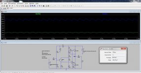
Non the less, this is one area the amp/PSU could be improved.
The JLH in my system has a physically separate and fully regulated power supply. This is pretty common .
I'm planning on trialing a choke input power supply to drop the hum/hash radiated by power supply.
Batteries (a la Jean Hiraga) completely solve the problem.
I'm planning on trialing a choke input power supply to drop the hum/hash radiated by power supply ... Batteries (a la Jean Hiraga) completely solve the problem.
That surely must be telling you something.
JLH ditched battery power 'in the interests of economy (EW Sept 1996)' – not for any sonic reason.
Big caps on power supply should remove the hum totally. If not - the problem can be somewhere else. I had a problematic potentiometers that caused a mains similar hum. Changed it and zero audible hum. Strange right? 🙂
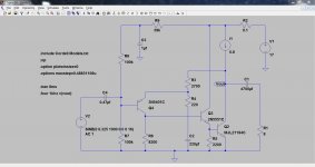
If you install LTspice here is the file that will run straight off. Just unzip the folder and keep the two files together. If you want to try it and get stuck just ask...
OK. I've tried it and I'm stuck!
I'm looking at the current at node V(out) (JLH 'X', Tr2e/Tr1c). This is Q1 emitter, Q2 collector, C5 o/p (JLH C2) and a couple of mA from nfb loop. These should all sum to zero but at peak output I get:
Q1e = -1.58A
Q2c = 0.42A and
C5 = - 0.99A
which sums to 0.17A ??? (expect slight variation)
I must be doing something wrong please can you check?
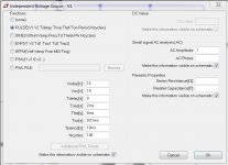
BTW I turned V2 amplitude up to 0.64 to get full drive.
Last edited:
Most of that is the current through C1, the bootstrap capacitor. Plus a couple of mA through R3.These should all sum to zero but at peak output I get:
Q1e = -1.58A
Q2c = 0.42A and
C5 = - 0.99A
which sums to 0.17A ???
OK. I've tried it and I'm stuck!
I'll have a look, hopefully in an hour or so... I got tied up with something unexpected.
- Home
- Amplifiers
- Solid State
- JLH 10 Watt class A amplifier