
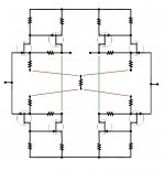
I think it has to do with the feedback configuration and you can't easily derive the differences between plus and minus outputs from one quadrant. You need 4 quadrants to see it easiest.
Something like that?You need 4 quadrants to see it easiest.
(Boy, it's so easier and faster with pen and paper..)
Attachments
Last edited:
Well, you have it turned inside-out, and it will still be somewhat confusing. Also, you should tie the respective inputs together for clarity.
Yes, I did, but not on purpose. I don't have a drawing programm, so it was just basic copy and paste. Some might find it easier to recognize the basic gain cell.
EDIT. Of course, it is all the small details that transforms this into final product.
EDIT. Of course, it is all the small details that transforms this into final product.
Last edited:
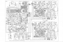
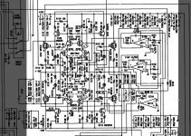
If someone will flip over the schematic for the PLD2000, I would appreciate it.
This is a REAL schematic, made by Taiwan, and is all that I have for this unit.
This is a REAL schematic, made by Taiwan, and is all that I have for this unit.
I can't, my "dumb" programm wants to create a bigger file. 😡
This schematic is a missing part of a puzzle. Now, the evolution in your Parasound line of products can clearly be seen.
This schematic is a missing part of a puzzle. Now, the evolution in your Parasound line of products can clearly be seen.
So, John, given the art the feedback is applied, is the attenuation of the signal, before it gets to the "other side", caused by non-infinite impedance of the resistor (network) in the middle that joins all four quadrants together?
Last edited:
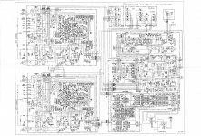
If someone will flip over the schematic for the PLD2000, I would appreciate it.
This is a REAL schematic, made by Taiwan, and is all that I have for this unit.
Rotated 180°.
Attachments
Last edited:
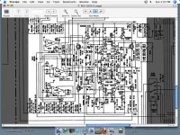
Here is another view:
Rotated 180°.
I used MS Paint. But you should download IRFANVIEW.
Attachments
Last edited:
Rotated 180°.
I used MS Paint. But you should download IRFANVIEW.
Neither of those programs runs on OSX.
But Preview dose give the option of rotating images.
Real schematics are 'messy'. This is because they have to meet so many needs and features.
The PLD2000 was my first effort to make an 'all out' JC-80 based preamp for Parasound. I did only 1/2 the design, and that should be obvious, but I did the 'heart' of the design, the 4 quadrant gain stage.
This preamp never got very popular, although it had lots of features, my name associated with it, and very competitively priced.
The Parasound JC-2 is based on this design and it has been much more successful.
WHY, is what I always hope to convey on this website, but to little avail.
However, one practical suggestion for those interested in a REAL preamp, is to get a PLD2000 used. They should be very cheap on E-bay, and they have 'potential' to be an even 'better' preamp than stock.
Also, even broken, and 'unfixable' getting the chassis for the PARTS alone should be a very worthwhile purchase.
On paper, the differences between the Parasound JC-2 and the PLD2000 are trivial, but there is a world of difference in subjective performance.
While the current 'belief' is that differences that are not easily identifiable and measurable, are fictitious, I will not dwell on my personal opinion of the differences between the Para JC-2 and the PLD2000.
I will try to point out some differences, large and small, that made the Para JC-2 a 'winner' and the PLD2000, a 'failure'.
1. Parts quality: The Para JC-2 has better 'quality' caps, but not necessarily of a different material.
2. Parts placement: The Para JC-2 has a 'better' layout.
3. Parts removed: The Para JC-2 has many less PARALLEL caps, that appear to be put in for the 'eye' rather than for the 'ear'.
4. Parts change: Jfets and Mosfets replace any remaining bipolar devices.
5. Better connectors: Nonmagnetic, quality made RCA and XLR connectors replace the cheaper, 'magnetic' ones used in the PLD2000.
6. Better connecting wire where possible.
That is all that I can think of.
The closest comparison that I can make is the difference between a Porsche 924 and a Porsche 944. I've owned and driven both extensively, and I certainly know the difference, but I don't know how to convey it to a general audience.
Last edited:
- Status
- Not open for further replies.
- Home
- Member Areas
- The Lounge
- John Curl's Blowtorch preamplifier part II